


Quick Research
Generate reliable direction feasibility study reports for your R&D in just a few steps.

Technical Q&A
Discover and master advanced knowledge NOW. Basics, ideas, possibilities, all at once.

Find Solutions
As an expert in R&D theories, this can generate solutions to your technical problems instantly.

Evaluate Feasibility
Analyze your overall solution with one click, know your potential R&D risks in advance.

Monitor Landscape
Get weekly tech updates, stay abreast of the latest tech innovations and key insights.
A variable-diameter spiral groove type automatic optical parts cleaning device
A technology for optical parts and cleaning devices, applied in cleaning methods and appliances, chemical instruments and methods, cleaning methods using liquids, etc., can solve problems such as unfavorable cleaning, achieve simple structure, easy maintenance, and eliminate cleaning dead ends.
- Summary
- Abstract
- Description
- Claims
- Application Information
AI Technical Summary
Problems solved by technology
Method used
Image

Examples
Embodiment 1
[0031] This example gives an embodiment of a transport mechanism.
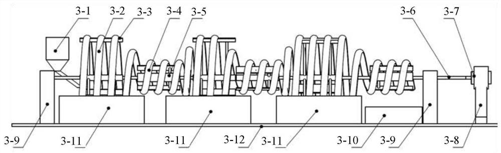
[0032] Such as image 3 In the actual operation, the respective components are placed on the table 3-12, and the transport mechanism includes a cleaning spiral bracket 3-3, transmitting a helical bracket 3-5, a drive shaft 3-6, two drive shaft brackets 3-9, motor 3-7 and motor brackets 3-8, mount the motor 3-7 on the motor bracket 3-8, and connect the drive shaft 3-6 with the motor, two drive shaft brackets 3-9 are set afterwards The position of the mounting spiral group is mounted, and the part supporting the drive shaft 3-6 and the transmission shaft 3-6, and the position of the mounting variable spiral group is interlaced with the cleaning spiral bracket 3-3 and the transmission spiral bracket 3- 5.
Embodiment 2
[0034] The present embodiment gives an embodiment of a variable velocity spiral group based on the embodiment 1.
[0035] In the present embodiment, the variable-axis spiral group includes a cleaning spiral 3-2, a transmission spiral 3-4, and a connection spiral, and the cleaning spiral 3-2 is mounted on the cleaning spiral bracket 3-3, and the transmission spiral 3-4 is mounted in the transmission spiral On the 3-4 bracket, the cleaning spiral 3-2 is connected to the spiral connection, and the cleaning tank 3-11 is disposed below the cleaning spiral 3-2.
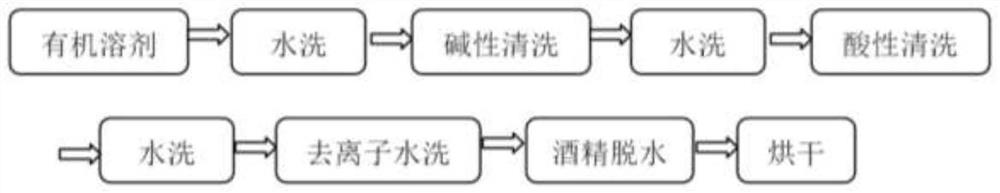
[0036] Further, during the actual cleaning optical parts, optical parts may be inconsistent in different washing liquids such as washing, alkaline cleaning, acidic cleaning, etc., which may be made according to the cleaning time. The number of turns, the cleaning time of the target, the number of turns of the cleaning spiral 3-2 in each variable-axis spiral group is obtained by the time required for the cleaning process, and th...
Embodiment 3
[0040] The present embodiment is further defined on the basis of Example 2.
[0041] Cleaning Spiral 3-2 of the Variable Path Spiral Group, Transmission Spiral 3-4 and the cross section of the helix, such as Image 6 As shown, for semicircular, U-shaped, rectangular shapes and its width is slightly greater than the optical parts that require cleaning, ensuring that the optical parts can be freely rolled in the slot; the groove material is made of acid and alkali, organic solvent material, such as polypropylene , Metal plates of acid-based protective coating, etc., open exciting small holes of the cleaning liquid on the groove body.
PUM
 Abstract
Description
Claims
Application Information
 - R&D Engineer
- R&D Manager
- IP Professional
- Industry Leading Data Capabilities
- Powerful AI technology
- Patent DNA Extraction
Browse by: Latest US Patents, China's latest patents, Technical Efficacy Thesaurus, Application Domain, Technology Topic, Popular Technical Reports.
© 2024 PatSnap. All rights reserved.Legal|Privacy policy|Modern Slavery Act Transparency Statement|Sitemap|About US| Contact US: help@patsnap.com