
Capacitive coupling plasma etching equipment

A plasma, capacitive coupling technology, used in circuits, discharge tubes, electrical components, etc.

Active Publication Date: 2020-06-23
ADVANCED MICRO FAB EQUIP INC CHINA
View PDF8 Cites 3 Cited by
  • Summary
  • Abstract
  • Description
  • Claims
  • Application Information

AI Technical Summary

Problems solved by technology

However, the distance between the plates in the current plasma etching equipment is fixed and cannot be adjusted, and since the electrodes are also part of the radio frequency circuit, in order to realize the adjustable distance between the plates, it is necessary to take into account the stability of the radio frequency circuit at the same time

Method used


Image

  • Capacitive coupling plasma etching equipment

Examples


Embodiment Construction

[0024] In order to make the above objects, features and advantages of the present invention more comprehensible, specific implementations of the present invention will be described in detail below in conjunction with the accompanying drawings.

[0025] In the following description, a lot of specific details are set forth in order to fully understand the present invention, but the present invention can also be implemented in other ways different from those described here, and those skilled in the art can do it without departing from the meaning of the present invention. By analogy, the present invention is therefore not limited to the specific examples disclosed below.

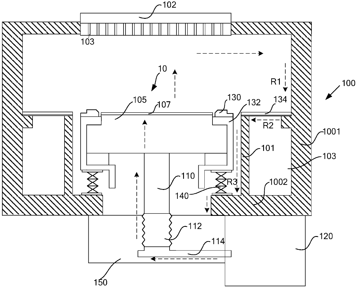
[0026] refer to figure 1 Shown is a schematic cross-sectional structure diagram of a capacitively coupled plasma etching device according to an embodiment of the present invention. The plasma etching equipment has a processing chamber, which is a closed space surrounded by a chamber body 100 and other necessar...


PUM


Abstract

The invention provides capacitive coupling plasma etching equipment, which is characterized in that a lower electrode is fixed at the lower end of a conductive supporting rod; a telescopic conductivepart is fixed at the lower end of the conductive supporting rod; the telescopic conductive part stretches out and draws back along the axial direction of the conductive supporting rod; the lower end of the telescopic conductive part is electrically connected with the output end of a radio frequency matcher through an electric connecting part at the same time; and the loop end of the radio frequency matcher is fixed at the bottom of the cavity. Therefore, the height of the lower electrode can be controlled through the extension and retraction of the telescopic conductive part, so that the distance between an upper pole plate and a lower pole plate is adjustable. Meanwhile, the loop end of the radio frequency matcher is fixed to the bottom of the cavity, movement of the electric connecting part in the radial direction of the telescopic conductive part is reduced when the telescopic conductive part stretches out and draws back in the axial direction, and the instability of the radio frequency loop cannot be caused, so that the stability of the radio frequency loop is considered while the distance between the pole plates is adjustable.

Description

technical field [0001] The invention relates to the field of semiconductor processing equipment, in particular to a capacitive coupling plasma etching equipment. Background technique [0002] Capacitively coupled plasma processing equipment generates plasma by means of radio frequency coupling discharge, and then uses plasma for deposition, etching and other processing techniques. Among them, the distance between the electrodes that generate plasma is an important parameter, especially In plasma etching equipment, with the continuous improvement of processing technology requirements, different etching steps need to be completed under different electrode plate spacings. However, the distance between the plates in the current plasma etching equipment is fixed and cannot be adjusted, and since the electrodes are also part of the radio frequency circuit, to realize the adjustable distance between the plates, it is necessary to take into account the stability of the radio frequen...

Claims


Application Information

Patent Timeline
Patent Type & Authority Applications(China)
IPC IPC(8): H01J37/32
CPCH01J37/32091H01J37/32431H01J37/32568H01J37/32449H01L21/68792H01L21/68742Y02P70/50H01J37/32183H01J37/32577H01J37/32642H01J37/32651H01L21/3065H01L21/6833H01L21/31116H01L21/67069H01J37/32532
Inventor 黄允文倪图强梁洁赵金龙吴磊
Owner ADVANCED MICRO FAB EQUIP INC CHINA
Learn More