GNSS receiver high sampling clock difference resolving method
A receiver clock difference and high-sampling technology, applied in the field of satellite navigation and positioning, can solve the problem of increased solution time
- Summary
- Abstract
- Description
- Claims
- Application Information
AI Technical Summary
Problems solved by technology
Method used
Image

Examples
Embodiment 1
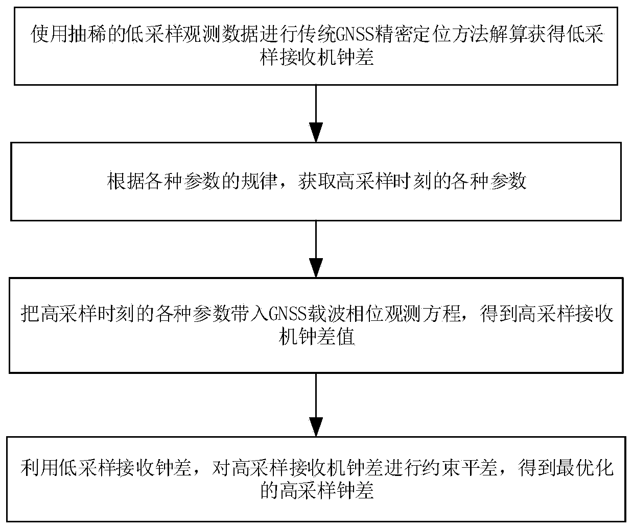
[0056] Such as figure 1 As shown, this embodiment is mainly aimed at the scene of static GNSS receivers on the ground, and proposes a high-sampling clock error calculation method for GNSS receivers. The specific implementation steps are as follows:
[0057] Step 101) Use the traditional method to solve the GNSS Precise Point Positioning (PPP, Precise Point Positioning) on the ground, and the data sampling rate is thinned to a low sampling time interval, which is 30 seconds to 15 minutes in this embodiment.
[0058] The ionosphere-free combination observation equation of GNSS is (Zumberger 1997; Kouba 2001):
[0059]
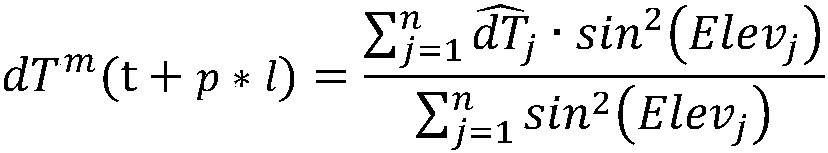
[0060]
[0061] In the formula,
[0062] is the ionosphere-free combined observation of the carrier phase;
[0063] is the ionosphere-free composite observation value of the code pseudorange;
[0064] is the wavelength of the ionosphere-free combined observation of the carrier phase;
[0065] is the ambiguity of the ionosphere-free combined ob...
Embodiment 2
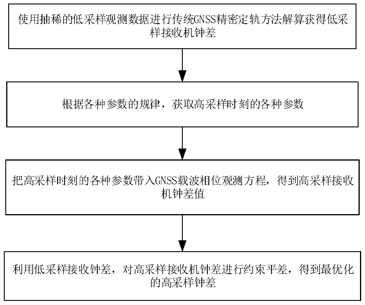
[0115] Such as figure 2 As shown, this embodiment is mainly aimed at the scenario of a space-borne GNSS receiver on a LEO satellite, and proposes a high-sampling clock error calculation method for a GNSS receiver. The specific implementation steps are as follows:
[0116] Step 201) Using the traditional method to solve the LEO precise orbit determination (POD, Precise Orbit Determination) of the spaceborne GNSS.
[0117] The GNSS ionosphere-free combined observation equation for LEO precise orbit determination is similar to that in step 1, the difference is that there is no tropospheric delay term T j ,Specifically:
[0118]
[0119]
[0120] The implication of each parameter in the formula is identical with embodiment 1.
[0121] In LEO precise orbit determination, the state vector contains six parameters of the satellite orbit (a 0 ,e 0 ,i 0 ,Ω 0 ,ω 0 , M 0 ) and force model parameters (light pressure parameters, atmospheric drag parameters, empirical force pa...
PUM
 Abstract
Description
Claims
Application Information
 - R&D
- Intellectual Property
- Life Sciences
- Materials
- Tech Scout
- Unparalleled Data Quality
- Higher Quality Content
- 60% Fewer Hallucinations
Browse by: Latest US Patents, China's latest patents, Technical Efficacy Thesaurus, Application Domain, Technology Topic, Popular Technical Reports.
© 2025 PatSnap. All rights reserved.Legal|Privacy policy|Modern Slavery Act Transparency Statement|Sitemap|About US| Contact US: help@patsnap.com