A device for generating plasma water vapor based on the principle of ejection

A plasma and generating device technology, applied in the field of plasma water vapor generating device, can solve the problems of unfavorable energy saving and environmental protection, heat loss, large volume, etc.

Active Publication Date: 2021-08-10
WUHAN UNIV
View PDF8 Cites 0 Cited by
  • Summary
  • Abstract
  • Description
  • Claims
  • Application Information

AI Technical Summary

Problems solved by technology

[0003] However, the principle of traditional steam generating devices to generate steam is mainly to use combustion heating or resistance heating to heat the water body to generate steam, and then transport it to the desired location. This method inevitably requires a large area. size, it is difficult to miniaturize, and the heating process has relatively serious heat loss, which is not conducive to energy saving and environmental protection. The steam flow rate generated by the unit is generally low, so the transportation time is longer, which further increases the heat loss

Method used


Image

  • A device for generating plasma water vapor based on the principle of ejection
  • A device for generating plasma water vapor based on the principle of ejection

Examples


Embodiment 1

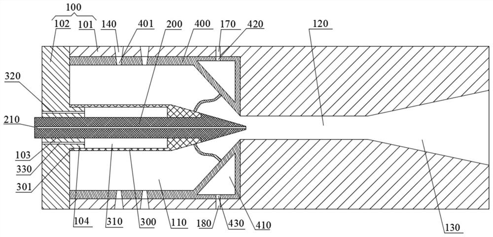
[0028] Such as figure 1As shown, the embodiment of the present application provides a plasma steam generating device based on the principle of ejection, which includes an ejector body 100 made of polyphenylene sulfide material, and the ejector body 100 includes a body 101 and a body 101 An annular end cap 102 connected at one end, the body 101 is provided with a throat channel 120 and a diffusion channel 130 connected in sequence, the inner diameter of the diffusion channel 130 gradually increases as it moves away from the throat channel 120, and the diffusion channel 130 communicates with the throat channel 120 and the Outside the body 101, the end cap 102 and the end of the body 101 enclose and form a suction chamber 110 communicating with the throat channel 120. The middle part of the end cap 102 is provided with a through hole 103, and the end cap 102 is connected with a polyphenylene sulfide material. The finished nozzle 200, one end of the nozzle 200 passes through the t...

Embodiment 2

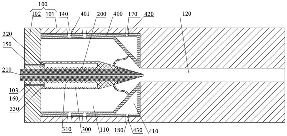
[0032] Such as figure 2 As shown, the embodiment of the present application provides a plasma water vapor generation device based on the principle of ejection, which has roughly the same structure as the plasma water vapor generation device based on the principle of ejection provided in Example 1, the difference is that this embodiment In the ejector body 100, there is no diffusion channel 130, one end of the throat channel 120 is connected to the suction chamber 110, and the other end is connected to the outside of the ejector body 100, the end cap 102 is not provided with a stopper 104, and the anode 300 is provided with There is a first cooling chamber 310 and a first liquid inlet hole 320 and a first liquid outlet hole 330 communicating with the first cooling chamber 310, and the end cover 102 is provided with a first cooling inlet connecting the first liquid inlet hole 320 and the outside 150 and the first cooling outlet 160 connecting the first liquid outlet 330 and the...


PUM


Abstract

The invention relates to a plasma water vapor generating device based on the ejection principle, which relates to the field of steam generators. The plasma water vapor generating device based on the principle of ejection includes an ejector body made of insulating material. The ejector body has a suction chamber and a throat channel connecting the suction chamber and the outside. The ejector body is connected with an insulating material. The finished nozzle, one end of the nozzle extends through the suction chamber into the throat channel, the nozzle is provided with a delivery channel for delivering the fluid to the throat channel, and the ejector body is provided with at least one air inlet connecting the suction chamber and the outside The suction chamber is provided with an anode made of conductive material sleeved on the nozzle, and the suction chamber is provided with a cathode made of conductive material. The plasma water vapor generating device based on the ejection principle provided by the present application can quickly, conveniently, efficiently and safely prepare high-temperature and high-speed water vapor for use.

Description

technical field [0001] The present application relates to the field of steam generators, in particular, to a plasma steam generating device based on the principle of ejection. Background technique [0002] Water vapor is widely used in industrial processes and daily life because of its low-cost and easy-to-obtain raw materials, a large amount of heat released during liquefaction, and almost completely non-toxic and harmless after liquefaction. In recent years, a steam cleaning method has been developed, which uses high-temperature and high-pressure steam to dissolve the oil stains on the surface to be cleaned, and vaporizes them to make the surface cleaned by saturated steam reach an ultra-clean state. Supersaturated steam Effectively cuts into any tiny holes and cracks, strips and removes stains and residue. In addition, water vapor has been widely promoted in many aspects such as atomization, moisturizing\humidification, power source, etc., and has a significant positive ...

Claims


Application Information

Patent Timeline
Patent Type & Authority Patents(China)
IPC IPC(8): F22B1/28
CPCF22B1/281F22B1/287
Inventor 龙新平程怀玉杨兵
Owner WUHAN UNIV
Why Eureka
Try Eureka