A method and system for state monitoring and fault diagnosis of tbm hob
A fault diagnosis system and hob technology, applied in measuring devices, earthwork drilling, mechanical bearing testing, etc., can solve the problems of long tool purchase cycle, affecting project progress, affecting project cost and construction period, etc., to avoid distortion of collected signals , to achieve accurate monitoring and ensure the effect of timeliness
- Summary
- Abstract
- Description
- Claims
- Application Information
AI Technical Summary
Problems solved by technology
Method used
Image
Examples
Embodiment 1
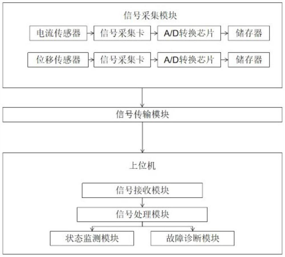
[0040] see figure 1 As shown, it is a structural block diagram of a TBM hob state monitoring and fault diagnosis system provided by this embodiment. It can be seen from the diagram that the overall system specifically includes: a signal acquisition module, a signal transmission module and a host computer;
Embodiment approach
[0042] (1) The signal acquisition module is installed on the cutter head of the TBM hob, and is used to collect the vibration signal of the main bearing of the cutter head and the current signal of the main motor, and convert the collected signal into a transmittable digital signal;
[0043] The specific signal acquisition module includes sensors, acquisition boards, AD conversion chips and memory; where:
[0044] The sensors include a vibration sensor and a current sensor, which are respectively installed on the main bearing and the main motor of the TBM cutter head, so as to collect the vibration signal of the main bearing of the TBM cutter head and the current signal of the main motor;
[0045] The acquisition board includes an integrated amplifier circuit and a filter circuit to convert the collected vibration signal and current signal into an analog signal;
[0046] The AD conversion chip converts the analog signal into a digital signal, and saves the digital signal into ...
Embodiment 2
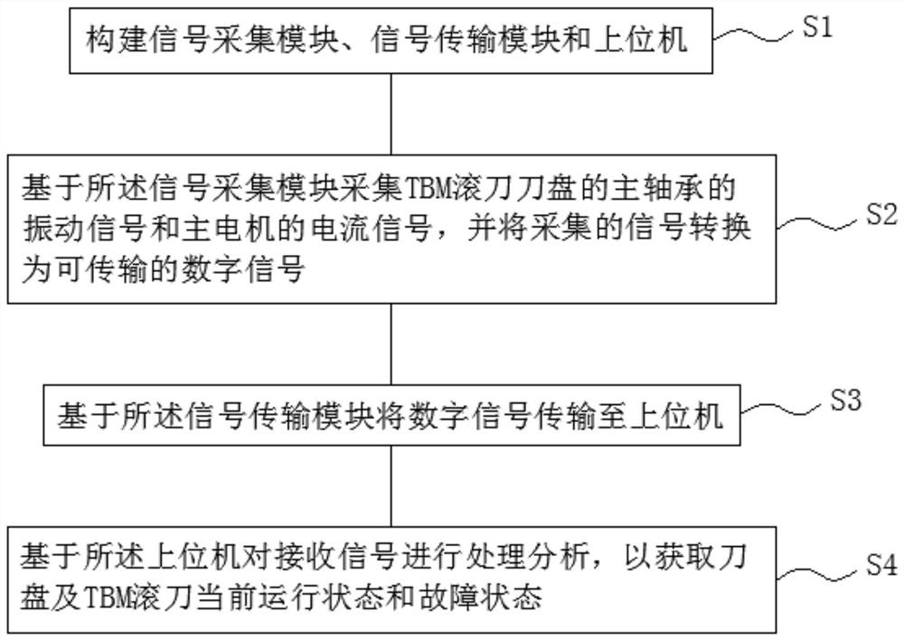
[0066] see image 3 As shown, it is a flow chart of a TBM hob state monitoring and fault diagnosis method provided in this embodiment. As can be seen from the figure, the overall method specifically includes the following steps:
[0067] S1. Build a signal acquisition module, a signal transmission module and a host computer;
[0068] S2. Based on the signal acquisition module, the vibration signal of the main bearing of the TBM hob cutterhead and the current signal of the main motor are collected, and the collected signal is converted into a transmittable digital signal;
[0069] S3. Transmit the digital signal to the host computer based on the signal transmission module;
[0070] S4. Process and analyze the received signal based on the host computer to obtain the current operating status and fault status of the cutter head and the TBM hob.
[0071] Wherein, step S4 includes:
[0072] S41. Using one of time-domain analysis, frequency-domain analysis or time-frequency domain...
PUM
 Abstract
Description
Claims
Application Information
 - R&D
- Intellectual Property
- Life Sciences
- Materials
- Tech Scout
- Unparalleled Data Quality
- Higher Quality Content
- 60% Fewer Hallucinations
Browse by: Latest US Patents, China's latest patents, Technical Efficacy Thesaurus, Application Domain, Technology Topic, Popular Technical Reports.
© 2025 PatSnap. All rights reserved.Legal|Privacy policy|Modern Slavery Act Transparency Statement|Sitemap|About US| Contact US: help@patsnap.com


