
Vehicle-mounted wireless charging device

A charging device, vehicle wireless technology, applied in circuit devices, battery circuit devices, current collectors, etc., can solve the problems of intermittent and unstable charging, large occupation area, low space utilization, etc.

Active Publication Date: 2020-06-19
HUNAN INST OF TECH
View PDF11 Cites 0 Cited by
  • Summary
  • Abstract
  • Description
  • Claims
  • Application Information

AI Technical Summary

Problems solved by technology

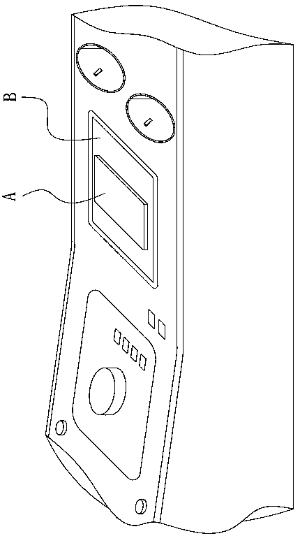
The area of ​​the bearing plane B set by this type of wireless charging device is usually 1.5 times to 2 times the area of ​​the back of the mobile phone A, which occupies a large area and the space utilization rate is not high. Satisfy the position of charging a mobile phone A
In addition, when the vehicle is driving on a bumpy road, especially on a non-paved road, the bumps of the vehicle will cause the mobile phone A to shake, shift and jump, and even fall from the carrying platform, resulting in intermittent and unstable charging.
[0004] In the prior art, most of the solutions to solve the instability of wireless charging caused by vehicle bumps are to clamp the mobile phone A with claws to prevent its displacement and jumping due to vehicle bumps. This method has a problem of complex structure in practical applications.

Method used


Image

  • Vehicle-mounted wireless charging device
  • Vehicle-mounted wireless charging device
  • Vehicle-mounted wireless charging device

Examples


Embodiment Construction

[0033] In order to facilitate the understanding of those skilled in the art, the present invention will be further described below in conjunction with the embodiments and the drawings, and the content mentioned in the embodiments does not limit the present invention.

[0034] In addition, in the present invention, unless expressly stipulated and defined otherwise, the terms "upper", "lower", "front", "rear", "left", "right", "vertical", "horizontal", The orientation or positional relationship indicated by "top", "bottom", "inner", "outer", etc. is based on the orientation or positional relationship shown in the drawings, and is only for the convenience of describing the present invention and simplifying the description, rather than indicating or implying that The device or element referred to must have a specific orientation, be constructed and operated in a specific orientation, and therefore cannot be understood as a limitation of the present invention.

[0035] figure 2 with F...


PUM


Abstract

The invention provides a vehicle-mounted wireless charging device, and relates to the technical field of wireless charging. The device comprises a power transmission coil, a charging bag and a hollowshell. The bag body of the charging bag comprises a fabric layer and an elastic wrapping layer arranged on the outer side of the fabric layer; at least four clamping pieces used for clamping electronic equipment from different directions are arranged between the fabric layer and the elastic wrapping layer; the clamping pieces are fixedly connected with the fabric layer; the power transmission coilis fixedly installed on one clamping piece and is insulated and isolated; the fabric layer is separated from the elastic wrapping layer; an opening is arranged in the top end of the shell; the bag body of the charging bag is downwards placed in the inner cavity of the shell from the opening in the top end of the shell; the periphery of the bag opening of the charging bag is fixedly connected withthe outer edge of the opening in the top end of the shell; a plurality of pull ropes are arranged in the inner cavity of the shell; and the pull ropes connect the clamping pieces and the fabric layerwith the inner wall face of the shell from different directions so as to prevent the bag body from colliding with the inner wall face of the shell when the bag body shakes in the inner cavity of theshell. The vehicle-mounted wireless charging device has the advantages of high space utilization rate and high charging stability.

Description

Technical field [0001] The present invention relates to the technical field of wireless charging, in particular to a vehicle-mounted wireless charging device. Background technique [0002] With the maturity of wireless charging technology, more and more vehicles are equipped with wireless charging devices to charge personal consumer electronic products (such as mobile phones). Wireless charging devices are generally installed in the armrest box or near the cup holder for easy access. Put cell phone A. [0003] Most of the existing in-vehicle wireless charging devices are like figure 1 As shown, it has a horizontal bearing plane B, the power transmission coil of the wireless charging device is arranged under the bearing plane B, after the mobile phone A is placed on the bearing plane B, the power receiving coil on the back of the mobile phone A is located above the power transmission coil, Electromagnetic induction realizes wireless transmission of electric energy between the power...

Claims


Application Information

Patent Timeline
Patent Type & Authority Applications(China)
IPC IPC(8): H02J7/00H02J7/02H02J50/10
CPCH02J7/0044H02J50/10
Inventor 毛珂肖冬瑞
Owner HUNAN INST OF TECH
Learn More