Eureka AIR delivers breakthrough ideas for toughest innovation challenges, trusted by R&D personnel around the world.

Hose filling and tail sealing system and hose filling and tail sealing method

A filling device and hose technology, applied in the field of hose filling and sealing systems, can solve the problems of ill-considered aseptic process, unreasonable structural layout and high interchangeability requirements, achieve reasonable overall structural layout and improve production. Efficiency and production quality, the effect of low error rates

Pending Publication Date: 2022-06-03
TRUKING TECH LTD
View PDF0 Cites 0 Cited by
  • Summary
  • Abstract
  • Description
  • Claims
  • Application Information

AI Technical Summary

Problems solved by technology

[0002] For most hose filling and sealing systems, there are the following defects: 1) The structural layout is unreasonable, the production efficiency is low, and the production capacity is generally low; The mechanism is complicated, the stability is poor, and the error rate is high; 3) The aseptic process is not considered, and the adaptability to products with requirements such as eye ointment is extremely low; 4) After the product specification is changed, it is necessary to replace and adjust many parts and structures, not only for equipment zero High requirements for parts interchangeability and high requirements for operators

Method used


Image

  • Hose filling and tail sealing system and hose filling and tail sealing method
  • Hose filling and tail sealing system and hose filling and tail sealing method
  • Hose filling and tail sealing system and hose filling and tail sealing method

Examples


Embodiment 1

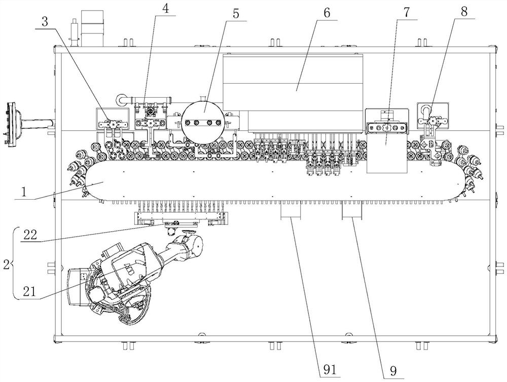
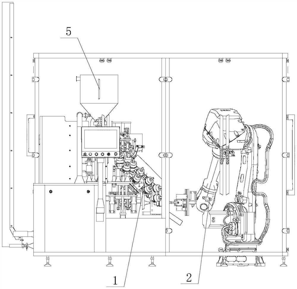
[0045] Figure 1 to Figure 11 As shown in the figure, the hose filling and sealing system of this embodiment includes an annular conveying device 1 for conveying hoses, and a variable-pitch feeding device 2, a benchmarking device 3, a blowing device 2 arranged in sequence along the conveying direction of the annular conveying device 1 Sweeping device 4, filling device 5, tail folding device 6, embossing device 7, visual inspection device 8, unloading device 9 and waste rejection device 91, one side of the annular conveying device 1 is the horizontal conveying side of the horizontal conveying hose, The other side is the upright conveying side of the upright conveying hose. The variable-pitch feeding device 2, the unloading device 9 and the rejecting device 91 are located on the horizontal conveying side of the annular conveying device 1. The loading device 5 , the tail folding device 6 , the imprinting device 7 and the visual inspection device 8 are located on the upright conve...

Embodiment 2

[0057] A method for filling and sealing a tube is carried out by using the above-mentioned system for filling and sealing a tube, comprising the following steps:

[0058] S1. Feeding: The variable-pitch feeding device 2 takes out the hose in the material box and transfers it to the feeding station on the horizontal conveying side of the annular conveying device 1, and then inserts the hose horizontally into the annular conveying device 1;

[0059] S2. Benchmarking: The annular conveying device 1 transfers the hose to the benchmarking station, and the benchmarking device 3 transfers the color mark of the hose to the same direction;

[0060] S3. Purge: The annular conveying device 1 transfers the hose to the purging station, and the inner wall of the hose is purged and cleaned by the purging device 4;

[0061] S4. Filling: The annular conveying device 1 transfers the hose to the filling station, and the filling device 5 fills the hose;

[0062] S5. Folding the tail: the annular...


PUM


Abstract

The invention discloses a hose filling and tail sealing system which comprises an annular conveying device, and a variable-pitch feeding device, a benchmarking device, a purging device, a filling device, a tail folding device, an impressing device, a visual detection device, a discharging device and a waste removing device which are sequentially arranged in the conveying direction of the annular conveying device, and one side of the annular conveying device is a horizontal conveying side; one side of the annular conveying device is a horizontal conveying side, the other side of the annular conveying device is a vertical conveying side, the variable-pitch feeding device, the discharging device and the waste removing device are located on the horizontal conveying side of the annular conveying device, and the benchmarking device, the purging device, the filling device, the tail folding device, the impressing device and the visual detection device are located on the vertical conveying side of the annular conveying device. The invention further discloses a hose filling and tail sealing method. The method comprises the steps that feeding is conducted; performing benchmarking; blowing and sweeping; performing filling; folding the tail; carrying out impressing; if the visual inspection is qualified, discharging is carried out, and if the visual inspection is unqualified, waste is removed. The hose filling and sealing system and the hose filling and sealing method have the advantages that the layout is reasonable, the production efficiency and the production quality are improved, and the like.

Description

technical field [0001] The invention relates to the technical field of food and medicine packaging machinery and equipment, in particular to a tube filling and sealing system and a tube filling and sealing method. Background technique [0002] For most hose filling and sealing systems, there are the following defects: 1) The structure layout is unreasonable, the production efficiency is low, and the production capacity is generally low; 2) The feeding structure of the equipment either has disadvantages such as friction and extrusion of the hoses, or feeding The mechanism is complex, the stability is poor, and the error rate is high; 3) The aseptic process is not considered, and the adaptability to products with requirements such as eye ointment is extremely low; The interchangeability of components is high, and there are also high requirements for operators. SUMMARY OF THE INVENTION [0003] The technical problem to be solved by the present invention is to overcome the de...

Claims


Application Information

Patent Timeline
Patent Type & Authority Applications(China)
IPC IPC(8): B65B9/10B65B35/16B65B35/24B65B35/56B65B43/16B65B43/52B65B43/54B65B51/16B65B55/24B65B57/14B65B61/26
CPCB65B9/10B65B43/16B65B43/54B65B43/52B65B55/24B65B51/16B65B61/26B65B57/14B65B35/24B65B35/56B65B35/16
Inventor 刘玉明曾凡云周振兴陈文峰高柱龙也
Owner TRUKING TECH LTD
Why Eureka
Eureka Blog
Learn More