Vehicle-mounted blind area image display method and system

A display system and blind spot technology, applied in the computer field, can solve the problems of not being able to effectively cover the blind spots in front of the left and right A-pillars and the blind spots of the rearview mirror, complicated installation, and high technical difficulties.

Inactive Publication Date: 2020-06-19
几何汽车科技(广州)有限公司
View PDF7 Cites 2 Cited by
  • Summary
  • Abstract
  • Description
  • Claims
  • Application Information

AI Technical Summary

Problems solved by technology

However, for the blind spots of the car's vision: the potential safety hazards in the front blind spots, AB pillar blind spots, and rearview mirror blind spots cannot be effectively resolved.
Children, stones, big pits, and vehicle merging in the above-mentioned blind areas cannot be fully resolved by existing products, which can easily cause accidents
As the current 360 panoramic image products that focus on solving the problem of blind spots need to be switched on and off through the buttons on the air-conditioning panel or the auxiliary instrument switch group, it is not automatic and convenient to enter the panoramic image system, especially for objects in the blind spot in front of the vehicle before starting the vehicle. It is impossible to automatically warn and avoid the occurrence of collision and rolling accidents
[0003] At the same time, the vehicle-mounted 360 panoramic image system is mainly used to assist parking. It cannot actively and effectively warn of collisions and rolling accidents caused by blind spots, and must install 4 cameras at the same time. In addition, the multi-region display mode of the panoramic image system is very easy It makes image resolution difficult, not intuitive enough, and even causes driving accidents. At the same time, because the 360 ​​panoramic image system needs to take into account the needs of image synthesis, the cameras on the left and right sides cannot effectively cover the blind spots in front of the left and right A-pillars and the blind spots of the rearview mirror.
The blind spot in the rearview mirror is very prone to traffic accidents when the vehicles are driving in parallel. Vehicle image processing, including 360 panoramic image products, cannot effectively solve this problem. The blind spot monitoring system that effectively solves this problem ( BSD) has the disadvantages of high technical difficulty and high cost, and it cannot display images, so it is difficult to form a universal application
, and 360 panoramic images also have problems such as high cost and complicated installation, resulting in a low installation utilization rate

Method used


Image

  • Vehicle-mounted blind area image display method and system
  • Vehicle-mounted blind area image display method and system
  • Vehicle-mounted blind area image display method and system

Examples


Embodiment Construction

[0031] In order to make the purposes, technical solutions and advantages of the embodiments of the present application clearer, the technical solutions in the embodiments of the present application will be clearly and completely described below in conjunction with the drawings in the embodiments of the present application. Obviously, the described embodiments It is a part of the embodiments of this application, but not all of them. Based on the embodiments in the present application, all other embodiments obtained by persons of ordinary skill in the art without making creative efforts belong to the protection scope of the present application.

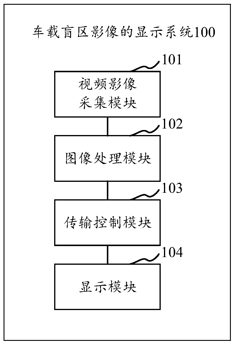
[0032] like figure 1 As shown, in one embodiment, a display system 100 for a vehicle blind spot image is provided. refer to figure 1 , the vehicle blind spot image display system specifically includes:

[0033] The video image acquisition module 101 is used to collect the video images of each blind area of ​​the vehicle through the i...


PUM


Abstract

The invention relates to a vehicle-mounted blind area image display method and system. The system comprises: a video image acquisition module which is used for acquiring video images of each blind area of a vehicle through image acquisition equipment installed in a plurality of blind areas to obtain blind area video images corresponding to the plurality of blind areas, and acquiring a reversing video of the vehicle through a vehicle reversing camera to obtain a reversing video image; an image processing module which is used for processing the blind area video images and the reversing video images according to the transmission mode of the video images and sending the images to a transmission control module, wherein when the blind area video images are analog signals, the blind area video images are sent to the transmission module; the transmission control module which is used for acquiring a starting signal and a driving signal of the vehicle and sending the corresponding blind area video image or the corresponding reversing video image to the display module according to the signal; and a display module which is used for displaying the received blind area video images or reversing video images.

Description

Technical field [0001] The present application relates to the field of computer technology, and in particular to a method and system for displaying vehicle blind spot images. Background technique [0002] In the existing technology, although some vehicles have been equipped with reversing radar, reversing images and even 360 panoramic image systems. However, the safety hazards existing in the car's blind areas of vision: forward blind areas, AB pillar blind areas, and rearview mirror blind areas cannot be effectively solved. Children, stones, large pits, vehicles merging, etc. that appear in the above-mentioned blind spots cannot be fully solved by existing products and can easily cause accidents. As the current 360 panoramic imaging product focuses on solving the problem of blind spots, it needs to be switched on and off through the keys on the air-conditioning panel or the sub-instrument switch group, resulting in a lack of automation and convenience when entering the pan...

Claims


Application Information

Patent Timeline
IPC IPC(8): B60R1/00
CPCB60R1/00B60R2300/105B60R2300/202B60R2300/207B60R2300/30B60R2300/802B60R2300/8066
Inventor 何湛全
Owner 几何汽车科技(广州)有限公司
Why Eureka
Try Eureka