
Polyethylene (PE) thin film blow molding machine

A technology of film blow molding and polyethylene, applied in the field of blow molding equipment, can solve the problems of incapable and efficient processing, increase the risk factor of personnel, etc., and achieve the effect of high-efficiency extrusion process, simple equipment structure, and continuous improvement

Inactive Publication Date: 2020-06-19
夏江华
View PDF0 Cites 0 Cited by
  • Summary
  • Abstract
  • Description
  • Claims
  • Application Information

AI Technical Summary

Problems solved by technology

[0002] In the working process of blow molding equipment, there are many shortcomings. When blow molding cylindrical objects with different diameters, it is necessary to perform multiple complex adjustments to achieve the high efficiency of blow molding processing, and The mold needs to be disassembled and replaced frequently so that the equipment can process blow molding products of different diameters. There are still many problems during the operation of the equipment. For example, the first processing in the blow molding process requires manual traction. , which increases the risk factor of personnel. Due to the high temperature of the product in the initial stage of blow molding, it is impossible for personnel to efficiently pull the product blown for the first time, so that personnel may be affected by the scald of the initial high-heat blow molding product. The life and health of personnel, while the existing equipment has low working efficiency and cannot perform efficient processing

Method used


Image

  • Polyethylene (PE) thin film blow molding machine
  • Polyethylene (PE) thin film blow molding machine
  • Polyethylene (PE) thin film blow molding machine

Examples


Embodiment Construction

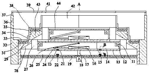
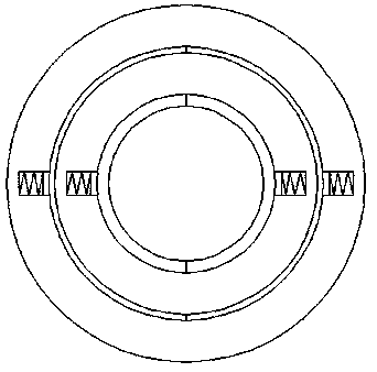
[0022] Such as Figure 1-Figure 3 As shown, the present invention is described in detail. For the convenience of description, the orientations mentioned below are now stipulated as follows: figure 1 The up, down, left, right, front and back directions of the projection relationship are the same. A polyethylene (PE) film blow molding machine of the present invention includes a fixed box 32, and the cooperating connection spring 31 is provided with several stacked settings for blow molding. Blowing device, the bottom molding blowing device is provided with a pushing and pouring device for pouring hot-melt polyethylene into the molding blowing device, and the upper end of the fixed box 32 is fixed with a symmetrical push cylinder 36, The power connection in the said push cylinder 36 is provided with a telescopic rod 37, and the upper end surface of the telescopic rod 37 is fixed with a top support rod 39, and the outer surface of the top support rod 39 is fixed with a connecting ...


PUM


Abstract

The invention discloses a polyethylene (PE) thin film blow molding machine. The blow molding machine comprises a fixed box body, wherein a plurality of forming blow-out devices which are arranged in astacked manner and used for blow-out forming are arranged in a mating connecting spring, and a pushing pouring device used for pouring hot melt polyethylene into the forming blow-out devices is arranged in the forming blow-out device at the lowermost side; and symmetrical pushing air cylinders are fixedly arranged on the upper end face of the fixed box body, a telescopic rod is arranged in each pushing air cylinder in a power connection manner, a top supporting rod is fixedly arranged on the upper end faces of the telescopic rods, a connecting guide rod is fixedly arranged on the outer surface of the top supporting rod, and the connecting guide rod is opposite to the forming blow-out devices. According to the blow molding machine, the structure is simple, a manner that the diameter of a blow-molded product can be quickly adjusted according to actual needs is adopted, and an efficient extrusion process can be realized; and the machine is also provided with a structure for facilitatingefficient traction of the blow-molded product, so that the continuous processing of the machine is improved.

Description

technical field [0001] The invention relates to the technical field of blow molding equipment, in particular to a polyethylene (PE) film blow molding machine. Background technique [0002] In the working process of blow molding equipment, there are many shortcomings. When blow molding cylindrical objects with different diameters, it is necessary to perform multiple complex adjustments to achieve the high efficiency of blow molding processing, and The mold needs to be disassembled and replaced frequently so that the equipment can process blow molding products of different diameters. There are still many problems during the operation of the equipment. For example, the first processing in the blow molding process requires manual traction. , which increases the risk factor of personnel. Due to the high temperature of the product in the initial stage of blow molding, it is impossible for personnel to efficiently pull the product blown for the first time, so that personnel may be ...

Claims


Application Information

Patent Timeline
Patent Type & Authority Applications(China)
IPC IPC(8): B29C55/28B29C55/00B29C48/00B29C48/28B29C48/25
CPCB29C48/0018B29C48/022B29C48/25B29C48/28B29C55/005B29C55/28B29K2023/06
Inventor 夏江华
Owner 夏江华
Learn More