
Deflection controllable and crack tip passivation expansion radius compensation mechanism

A technology of expanding radius and compensating mechanism, which is applied in metal processing equipment, feeding device, positioning device, etc., can solve the problem that the loading force cannot effectively control the deflection of the blanking end of the pipe, and the change of the passivation radius of the crack tip is uncontrollable. Easy to replace, realize compensation, reduce friction effect

Active Publication Date: 2020-06-19
CHINA UNIV OF PETROLEUM (EAST CHINA)
View PDF5 Cites 0 Cited by
  • Summary
  • Abstract
  • Description
  • Claims
  • Application Information

AI Technical Summary

Problems solved by technology

Under the combined action of the loading force and the compensation feedback force, the passivation radius of the crack tip can be controlled to change between the minimum passivation radius and the critical passivation radius with the feeding force during the entire crack propagation process, which solves the problem of metal pipe material During the whole process of material dynamic separation, there is often the problem that the applied load cannot effectively control the deflection of the lower material end of the pipe. The microcosmic manifestation is that the change of the passivation radius of the crack tip is uncontrollable. Instantaneous interruption due to sharp critical passivation radius

Method used


Image

  • Deflection controllable and crack tip passivation expansion radius compensation mechanism
  • Deflection controllable and crack tip passivation expansion radius compensation mechanism
  • Deflection controllable and crack tip passivation expansion radius compensation mechanism

Examples


Embodiment 1

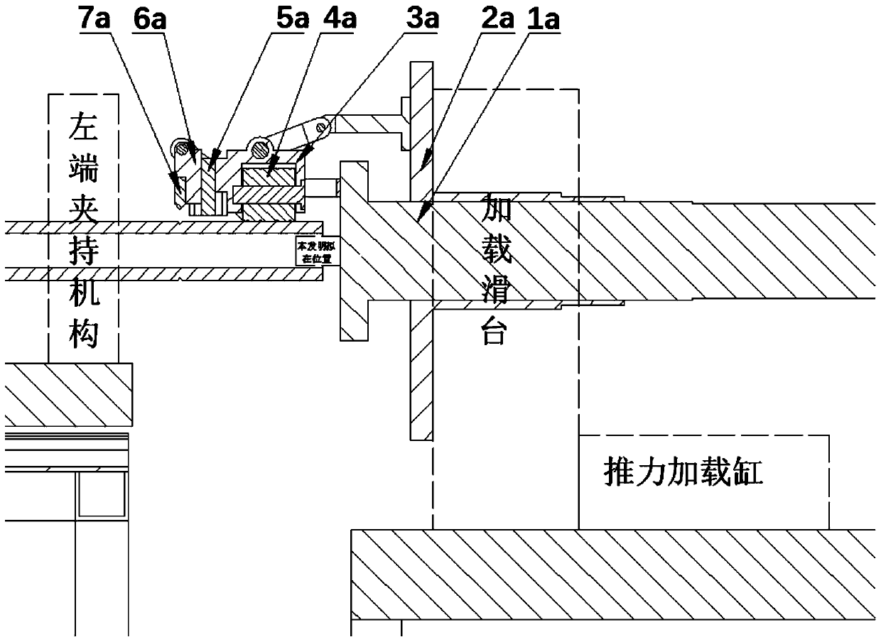
[0043] attached figure 1 It is a schematic diagram of the slotting and blanking of the pipe blanking machine in the prior art, as attached figure 1 shown. Fix one end of the pipe material in the clamping mechanism at the left end, and the other end is cantilevered under the slotting and unloading mechanism. The frequency conversion motor drives the loading transmission shaft 1a to rotate, and at this time, the turntable 2a matched with the loading transmission shaft 1a also follows it. The synchronous rotation makes the integrated linkage device for pipe material slotting and unloading fixed on the turntable 2a rotate synchronously. When slotting, the thrust loading cylinder pushes the loading slide to drive the turntable 2a to move backward, and the cutter slider 6a drives the slotting knife 7a to approach the pipe material along the double slide rails 5a. At this time, the blanking slider 3a drives the blanking hammer 4a to gradually move away. Pipe material, to realize th...


PUM


Abstract

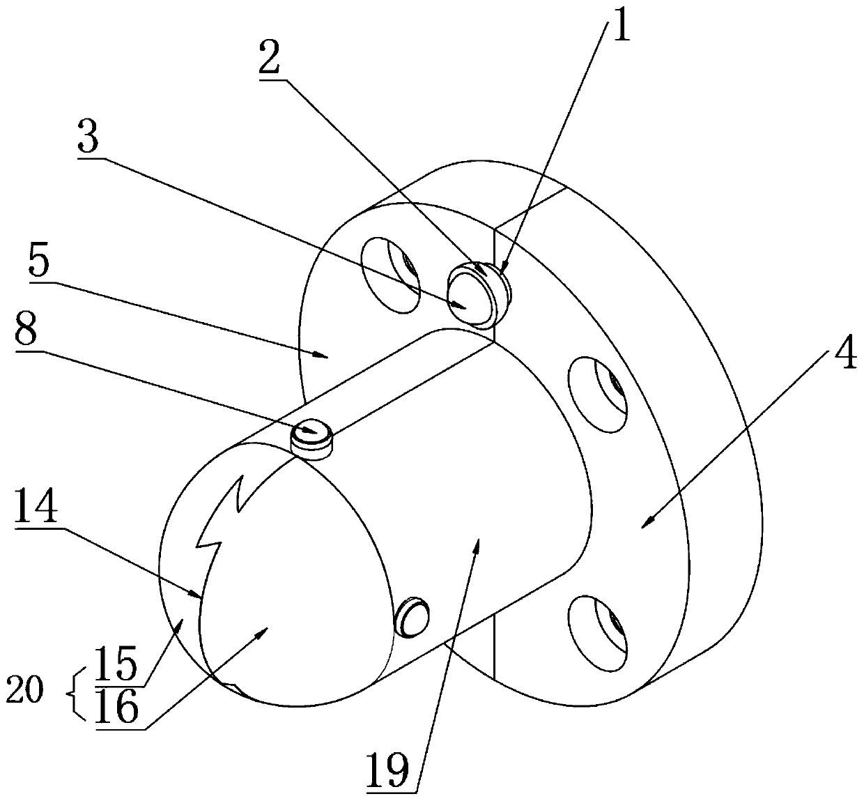
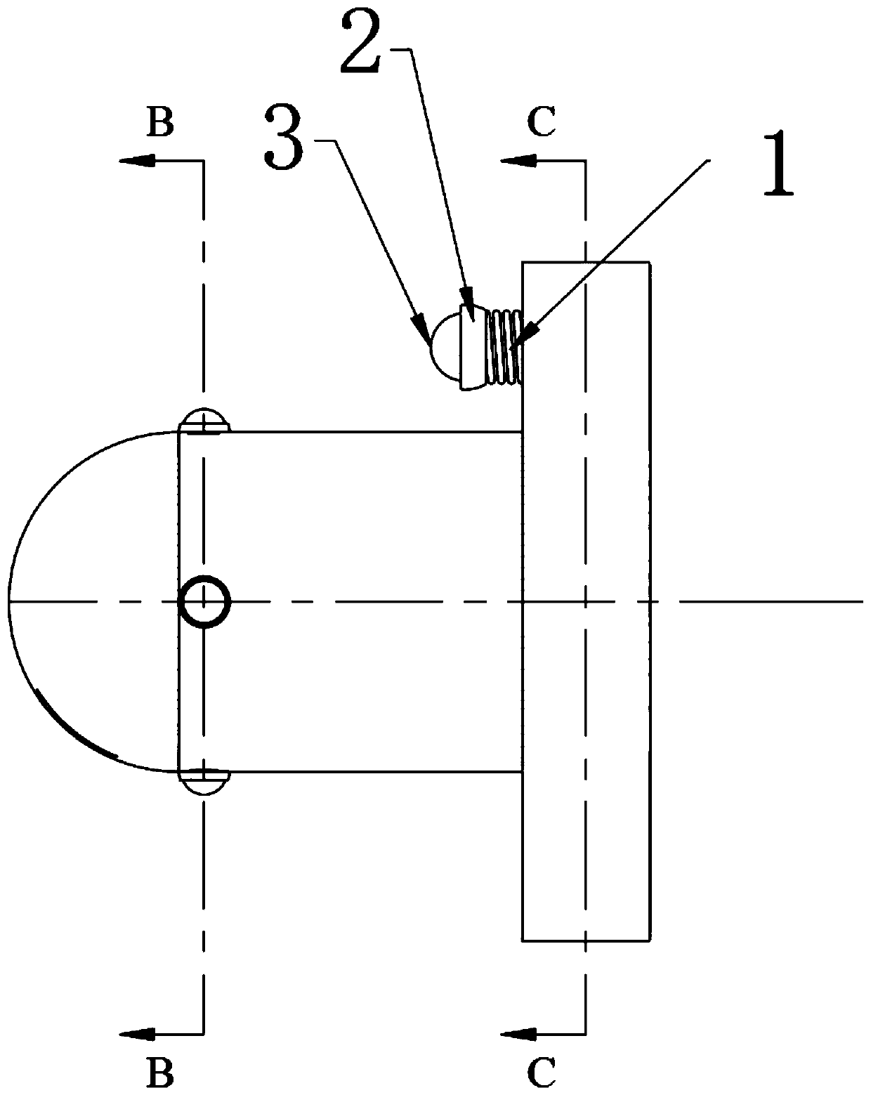
The invention provides a deflection controllable and crack tip passivation expansion radius compensation mechanism, and relates to the technical field of precision forming. The compensation mechanismcomprises a rod body unit and a ball head unit, wherein the rod body unit is formed by connecting a first rod body and a second rod body; and the ball head unit comprises a universal rotatable ball head, a ball head push rod and a spring. The compensation mechanism comprises a protruding part, the end of the protruding part is formed by integrating a hemisphere and a circular barrel, and universalrotatable ball fulcrums are arranged at the joint of the hemisphere and the circular barrel. According to the compensation mechanism, the problem that the deflection of the blanking end of a pipe cannot be effectively regulated and controlled due to the fact that the applied loading force often occurs in the whole dynamic separation process of a metal pipe is solved, and the problem that the microcosmic representation mode is that the change of the crack tip passivation radius is uncontrollable, and before a crack is expanded to the inner wall of a pipe material, the crack tip critical passivation radius is reached in advance, so that instability and instantaneous interruption are caused is solved.

Description

technical field [0001] The invention relates to the technical field of precision molding, in particular to a compensation mechanism with controllable deflection and crack tip passivation expansion radius. Background technique [0002] Low-stress blanking is to apply crack technology to pipe (or bar) blanking. First, a circumferential crack is artificially prefabricated on the surface of the pipe (or bar), and then the pipe with a circumferential surface crack ( or bar) to apply a certain external force to make it dynamically separate in the form of low stress brittle fracture. Low-stress bending fracture blanking is recognized as the most promising precision blanking method in the future. It makes full use of the notch effect and bending effect of the circumferential V-shaped groove to achieve brittle fracture of materials at low stress levels and obtain geometry-free Distortion, vertical flat fracture, blank without chamfering. At present, scholars have conducted some res...

Claims


Application Information

Patent Timeline
Patent Type & Authority Applications(China)
IPC IPC(8): B21D31/04B21D43/00
CPCB21D31/043B21D43/003
Inventor 张立军杨宁张德潇金永山郭伟健徐嘉怡姜浩张辛相恒富盖永革
Owner CHINA UNIV OF PETROLEUM (EAST CHINA)
Learn More