A cleaning device for degreasing treatment of valve parts

A cleaning device and degreasing treatment technology, applied in the direction of cleaning methods using liquids, cleaning methods using tools, cleaning methods and utensils, etc., can solve the problem of affecting the surface cleanliness of valve parts, slow removal of oil stains, and waste Time and manpower and other issues can be shortened, cleaning time can be improved, efficiency can be improved, and drainage work can be facilitated.

Active Publication Date: 2021-08-27
浙江奥德华科技股份有限公司
View PDF7 Cites 0 Cited by
  • Summary
  • Abstract
  • Description
  • Claims
  • Application Information

AI Technical Summary

Problems solved by technology

[0003] At present, when using the degreasing solvent immersion method to remove the oil stains on the surface of valve parts, usually the valve parts are directly poured into the box containing the degreasing solvent for soaking, and it is necessary to wait for the degreasing solvent to separate from the surface of the valve parts. The oil stain reacts, and the efficiency of removing the oil stain is slow, and when the degreased valve parts are taken out, it needs to be salvaged slowly, wasting time and manpower, and because the salvaged valve parts contain degreasing solvent on the surface, Direct salvage will result in the waste of degreasing solvent, and the impurities on the surface of valve parts will also be salvaged together, and the surface of the salvaged valve parts contains degreasing solvent, which will affect the cleaning of the surface of valve parts sex

Method used


Image

  • A cleaning device for degreasing treatment of valve parts
  • A cleaning device for degreasing treatment of valve parts
  • A cleaning device for degreasing treatment of valve parts

Examples


Embodiment Construction

[0027] In order to make the technical means, creative features, goals and effects achieved by the present invention easy to understand, the present invention will be further described below in conjunction with specific embodiments.

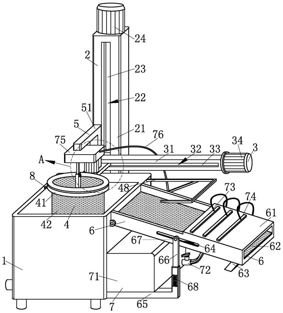
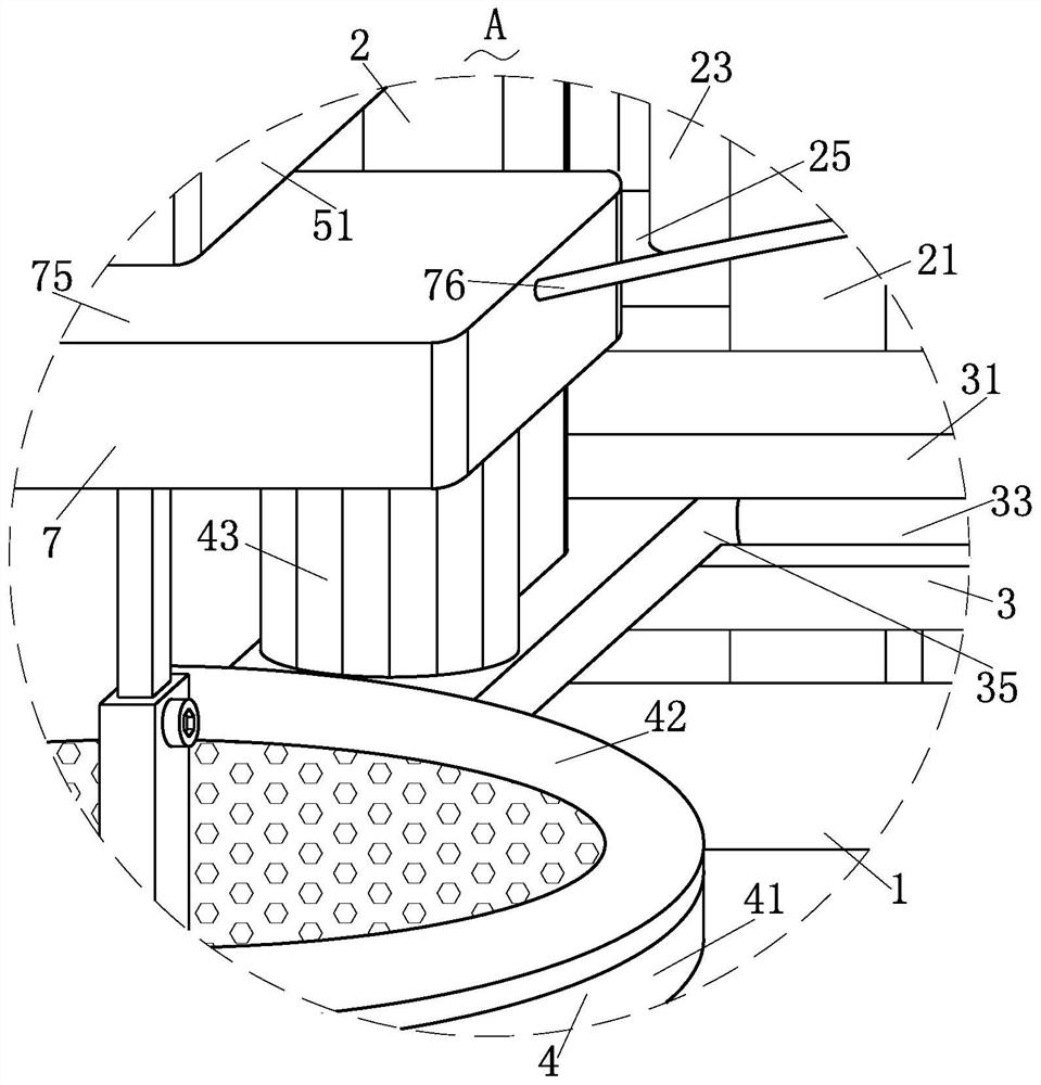
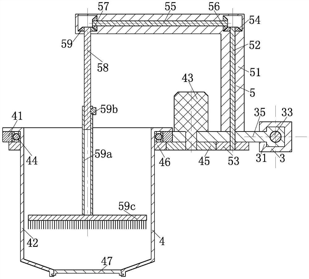
[0028] Such as Figure 1-Figure 6 As shown, a cleaning device for degreasing valve components according to the present invention includes a box body 1, a feeding structure 2, a traverse structure 3, a rotating structure 4, a cleaning structure 5, a discharging structure 6, and a flushing structure 7 and a beating structure 8, which is used to install the feeding structure 2 for taking out the valve parts from the inside of the box 1 at one end of the box 1 for containing the degreasing solvent and installing other parts; One end of the material structure 2 is installed with the traverse structure 3 for laterally moving the removed valve parts out of the top of the box body 1, and the traverse structure 3 for rotating and cleaning the valve parts i...


PUM


Abstract

The invention relates to the field of production and processing devices for valve parts, in particular to a cleaning device for degreasing treatment of valve parts, including a box body, a feeding structure, a traverse structure, a rotating structure, a cleaning structure, a discharge structure, and a flushing structure and flapping structure; through the setting of the rotating structure, the valve parts can be rotated and cleaned, so that the cleaning time of the valve parts can be shortened, and the valve parts can be cleaned more thoroughly, ensuring the cleaning quality of the valve parts. A feeding structure is set at one end of the box, which can extract the cleaned valve parts from the inside of the box, and then cooperate with the work of the traversing structure to move the valve parts taken out from the inside of the box to the outside of the box , so that it is convenient to drain the valve parts and take out the valve parts from the inside of the box, avoiding manual salvage of parts inside the box, so as to save labor and improve efficiency.

Description

technical field [0001] The invention relates to the field of production and processing devices for valve parts, in particular to a cleaning device for degreasing treatment of valve parts. Background technique [0002] Valves are pipeline accessories used to open and close pipelines, control flow direction, adjust and control the parameters (temperature, pressure and flow) of the conveying medium. According to its function, it can be divided into shut-off valve, check valve, regulating valve and so on. The valve is a control component in the fluid delivery system, which has functions such as cut-off, adjustment, flow diversion, reverse flow prevention, pressure stabilization, flow diversion or overflow pressure relief. Valves used in fluid control systems range from the simplest cut-off valves to various valves used in extremely complex automatic control systems, with a wide variety of varieties and specifications. Valves can be used to control the flow of various types of ...

Claims


Application Information

Patent Timeline
Patent Type & Authority Patents(China)
IPC IPC(8): B08B3/08B08B3/06B08B1/02B08B3/02F26B5/00
CPCB08B1/002B08B1/02B08B3/022B08B3/06B08B3/08F26B5/00
Inventor 陈艳
Owner 浙江奥德华科技股份有限公司
Why Eureka
Try Eureka