


Quick Research
Generate reliable direction feasibility study reports for your R&D in just a few steps.

Technical Q&A
Discover and master advanced knowledge NOW. Basics, ideas, possibilities, all at once.

Find Solutions
As an expert in R&D theories, this can generate solutions to your technical problems instantly.

Evaluate Feasibility
Analyze your overall solution with one click, know your potential R&D risks in advance.

Monitor Landscape
Get weekly tech updates, stay abreast of the latest tech innovations and key insights.
Efficient heat dissipation type distribution automation monitoring device
A power distribution automation and monitoring device technology, applied in substation/distribution device casing, electromechanical device, substation/switchgear cooling/ventilation, etc. question
- Summary
- Abstract
- Description
- Claims
- Application Information
AI Technical Summary
Problems solved by technology
Method used
Image


Examples
Embodiment 1
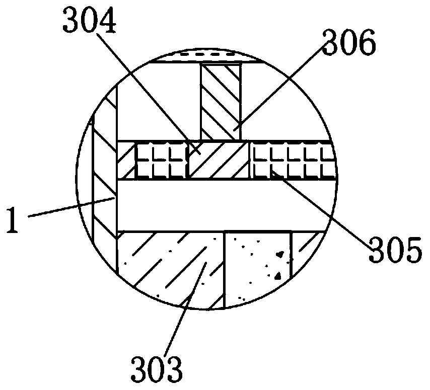
[0038] See Figure 1-6 , The present invention provides a technical solution: an efficient heat-dissipating power distribution automation monitoring device, comprising a box body 1, a first filter 2 and a sliding door 6. The left and right sides of the box body 1 are provided with multiple openings, and the box body The first filter screen 2 is installed at the upper and lower openings of 1, and the mesh number of the first filter screen 2 is 30 meshes. The internal air flow can be realized through the first filter screen 2. A sliding door 6 is installed on the front face of the box body 1. , The box 1 can be opened through the sliding door 6. A first heat sink 3 is installed below the inside of the box 1. The first heat sink 3 includes a first horizontal plate 301, an exhaust fan 302, a power distribution monitoring device 303, and a second horizontal Plate 304, second filter screen 305 and first vertical plate 306, the lower surface of the left and right first horizontal plat...
Embodiment 2
[0042] according to Figure 1-6 : When the operator needs to use a high-efficiency heat-dissipating power distribution automation monitoring device, the operator first pours an appropriate amount of water into the water tank 402, so that the water in the water tank 402 flows into the second arc-shaped water pipe 407, and the second arc-shaped water pipe The water in 407 absorbs the heat dissipated by the power distribution monitoring equipment 303, connects to the external power supply of the water pump 406, starts the water pump 406, and the water pump 406 sucks the water in the second arc-shaped water pipe 407 through the water suction port, and draws the water through the water outlet Drain into the first arc-shaped water pipe 404, make the water enter the water tank 402 through the first arc-shaped water pipe 404, so as to circulate the water, thus achieving the purpose of cooling the power distribution monitoring equipment 303 and turning on the external power supply of the...
PUM
 Abstract
Description
Claims
Application Information
 - R&D Engineer
- R&D Manager
- IP Professional
- Industry Leading Data Capabilities
- Powerful AI technology
- Patent DNA Extraction
Browse by: Latest US Patents, China's latest patents, Technical Efficacy Thesaurus, Application Domain, Technology Topic, Popular Technical Reports.
© 2024 PatSnap. All rights reserved.Legal|Privacy policy|Modern Slavery Act Transparency Statement|Sitemap|About US| Contact US: help@patsnap.com