Combustion chamber device for dispersing high-temperature reflux zone at boss

A high-temperature reflow and combustion chamber technology, which is applied in the direction of combustion chambers, continuous combustion chambers, and combustion methods, can solve the problems of increased thermal NOx emissions, reduce the generation of NOx, avoid heat accumulation, and increase flame stability. Effect

Pending Publication Date: 2020-06-16
SHANGHAI UNIVERSITY OF ELECTRIC POWER
View PDF0 Cites 1 Cited by
  • Summary
  • Abstract
  • Description
  • Claims
  • Application Information

AI Technical Summary

Problems solved by technology

However, the swirling flow will cause the premixed gas to generate a high-temperature recirculation zone at the inlet section of the combustion chamber and the boss of the flame tube, and a large amount of heat will accumulate in the recirculation zone, resulting in an increase in thermal NOx emissions

Method used


Image

  • Combustion chamber device for dispersing high-temperature reflux zone at boss
  • Combustion chamber device for dispersing high-temperature reflux zone at boss
  • Combustion chamber device for dispersing high-temperature reflux zone at boss

Examples


Embodiment Construction

[0015] In order to make the technical means and effects realized by the present invention easy to understand, the present invention will be described in detail below in conjunction with the embodiments and accompanying drawings.

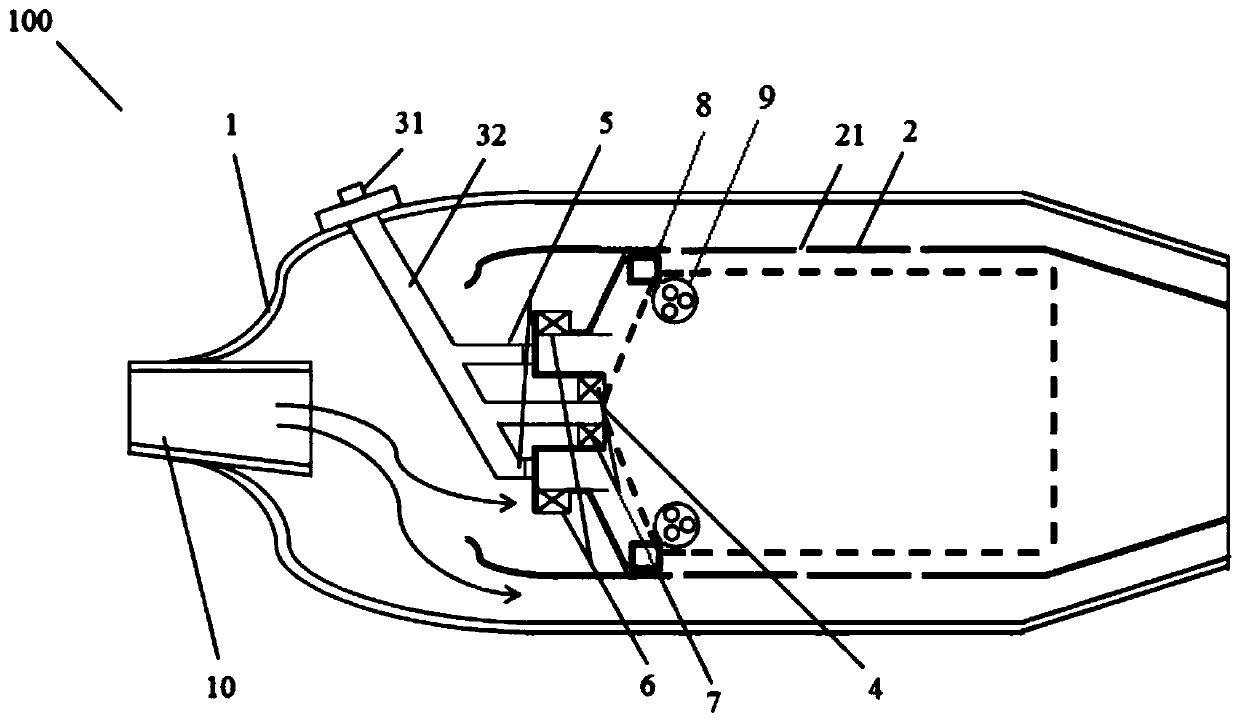
[0016] figure 1 It is a structural schematic diagram of a combustion chamber device in the high-temperature recirculation zone at the dispersion boss in the embodiment of the present invention.

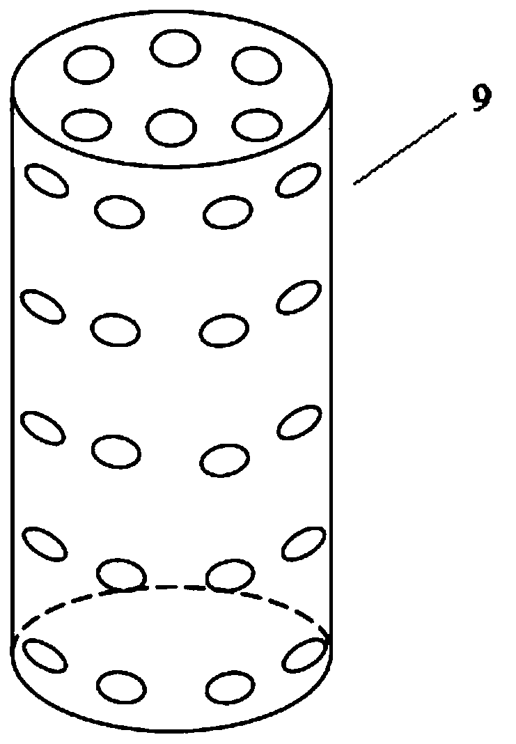
[0017] Such as figure 1 As shown, a combustion chamber device 100 in the high-temperature recirculation area at the dispersed boss in this embodiment has a casing 1, a flame tube 2, a fuel channel 3, an on-duty fuel channel 4, a fuel inlet channel 5, and a radial swirler 6. Axial cyclone 7 , boss 8 , porous cylinder 9 and diffuser channel 10 .

[0018] Receiver 1.

[0019] The flame tube 2 is arranged in the casing 1 and forms an annular cavity with the casing 1 .

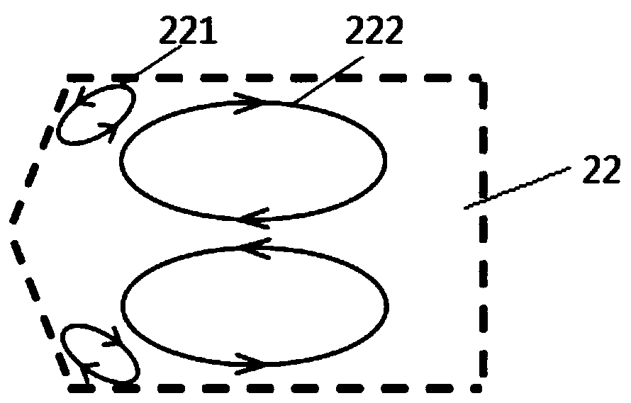
[0020] The wall surface of the flame tube 2 is provided with a mixing hole 21 .

[0021]...


PUM


Abstract

The invention discloses provides a combustion chamber device for dispersing a high-temperature reflux zone at a boss. The combustion chamber device for dispersing the high-temperature reflux zone at the boss comprises a casing, a flame tube, a fuel channel, an on-duty fuel channel, two fuel inlet channels, radial cyclones, axial cyclones, the boss, porous cylinders and a pressure expanding channel; the flame tube is arranged in the casing and forms an annular cavity with the casing; the fuel channel comprises a fuel spraying nozzle arranged on the casing and an input pipeline connected to thefuel spraying nozzle, and is used for inputting fuel; one end of the on-duty fuel channel is connected with the input pipeline, and the other end of the on-duty fuel channel is positioned at the central position of the head of the flame tube; one end of each fuel input channel is connected with the input pipeline; the other end of each fuel input channel is positioned at the head of the flame tube; the fuel inlet channels are respectively arranged on the two sides of the on-duty fuel channel; the radial cyclones are arranged at outlets of the fuel inlet channels in circumferential directions;the axial cyclones are arranged on the outer side of the on-duty fuel channel in an annular direction; the boss is positioned at the tail end of an inlet sudden enlargement structure of the flame tube; the porous cylinder is longitudinally fixed to the boss; and the pressure expanding channel is formed in the head of the casing and is used for intruding high-speed air flow.

Description

technical field [0001] The invention belongs to the field of combustion chambers of gas turbines, and in particular relates to a combustion chamber device in a high-temperature recirculation zone at a dispersing boss. Background technique [0002] As the country pays close attention to issues such as energy and environmental pollution, gas turbine power generation has gradually attracted widespread attention due to its advantages such as fast start-up, low environmental pollution, and high energy utilization rate. Compared with thermal power generation, gas turbine power generation uses natural gas as fuel, which has less pollution to the environment. This not only satisfies the country's use of clean energy, but also meets related policies such as environmental pollution. Gas turbine power generation has strong adaptability, can cooperate with power grid peak regulation, and has a wide range of applications. With the universal application of gas turbine power generation i...

Claims


Application Information

Patent Timeline
Patent Type & Authority Applications(China)
IPC IPC(8): F23R3/06
CPCF23R3/06F23R2900/03043
Inventor 付在国梁潇天高欢欢
Owner SHANGHAI UNIVERSITY OF ELECTRIC POWER
Why Eureka
Try Eureka