Low-carbon energy-saving sewage treatment system

A sewage treatment system and clear water technology, applied in the direction of water/sewage treatment, biological water/sewage treatment, water/sewage treatment equipment, etc., can solve the problem that the stratification effect of clean water and sludge is difficult to control and cannot be better stratified Effectiveness, poor sewage treatment effect and other problems, to achieve the effect of improving aeration effect and aeration efficiency, improving separation effect and service life, and good environmental protection

Active Publication Date: 2020-06-16
湖南美源环保股份有限公司
View PDF4 Cites 3 Cited by
  • Summary
  • Abstract
  • Description
  • Claims
  • Application Information

AI Technical Summary

Problems solved by technology

[0004] The disadvantage of the prior art is that clear water and sludge are stratified in the sedimentation tank, the upper layer is clear water, and the lower layer is sludge. However, since the clear water and sludge have a certain dispersion effect in the sedimentation tank, even in a steady state environment, The stratification effect of clean water and sludge in the sedimentation tank is difficult to control, so the separation of clear water and sludge by gravity settlement alone cannot obtain a good stratification effect, and the clear water often contains activated sludge and other other substances. Impurities, the sewage treatment effect is poor, not suitable for the conditions of high sewage treatment quality requirements

Method used


Image

  • Low-carbon energy-saving sewage treatment system
  • Low-carbon energy-saving sewage treatment system
  • Low-carbon energy-saving sewage treatment system

Examples


Embodiment

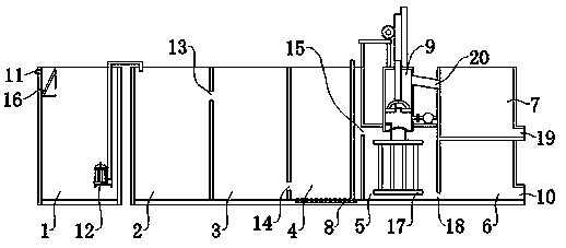
[0038] Embodiment: a kind of low-carbon energy-saving sewage treatment system, such as Figure 1-5 As shown, it includes a regulating tank 1, an anaerobic tank 2, an anoxic tank 3, an aerobic tank 4, a membrane bioreaction tank 5, a sludge tank 6, a clean water tank 7 and a clean water delivery mechanism 9. The anaerobic pool 2, the anoxic pool 3, the aerobic pool 4, the membrane bioreaction pool 5 and the sludge pool 6 are connected in sequence, and the regulating pool 1 is equipped with a lift pump 12 for transporting the sewage in the regulating pool 1 to Anaerobic tank 2. The regulating tank 1 is provided with a sewage inlet 11, and the sewage inlet 11 is provided with a grid 16, and the grid is used for preliminary filtration to prevent large solid impurities from entering the regulating tank 1. Preferably, the anaerobic tank 2, the anoxic tank 3, the aerobic tank 4, the membrane bioreaction tank 5 and the sludge tank 6 are respectively separated by partition walls. The...


PUM


Abstract

The invention discloses a low-carbon energy-saving sewage treatment system and belongs to the technical field of sewage treatment. The sewage treatment system comprises an adjusting tank, an anaerobictank, an anoxic tank, an aerobic tank, a membrane biological reaction tank, a sludge tank and a clean water tank, and further comprises a clean water conveying mechanism. The clean water conveying mechanism comprises a water pumping cavity, a push rod, a connecting frame, an upper sealing disc, an upper driving air cylinder, a water pumping channel, a lower sealing disc, a lower driving air cylinder, a sealing piston and a driving device. The lower sealing disc is movably connected to the water pumping cavity, and the lower driving air cylinder is used for driving the lower sealing disc to rotate on the water pumping cavity so that the water pumping channel can be opened or closed. The driving device is used for driving the push rod and the sealing piston to move up and down in the waterpumping cavity, the upper sealing disc is movably connected to the sealing piston, and the upper driving air cylinder is used for driving the upper sealing disc to rotate on the sealing piston to openor close the center hole. A water feeding channel is formed on one side of the upper part of the water pumping cavity. The system has the advantages of low carbon, energy conservation, high sewage treatment quality, convenience in backwashing and the like.

Description

technical field [0001] The invention relates to the technical field of sewage treatment, more specifically, it relates to a low-carbon and energy-saving sewage treatment system. Background technique [0002] Sewage treatment refers to the process of purifying sewage to meet the water quality requirements for discharge into a certain water body or reuse. Sewage treatment is widely used in various fields such as construction, agriculture, transportation, energy, petrochemical, environmental protection, urban landscape, medical treatment, catering, etc., and it is also increasingly entering the daily life of ordinary people. [0003] The authorized announcement number is CN206901993U, and the authorized publication date is January 19, 2018. The Chinese patent discloses an integrated MBBR sewage treatment equipment, including sequentially connected anaerobic tank, anoxic tank, aerobic tank and sedimentation tank. [0004] The disadvantage of the prior art is that clear water an...

Claims


Application Information

Patent Timeline
Patent Type & Authority Applications(China)
IPC IPC(8): C02F9/14
CPCC02F1/001C02F3/1268C02F3/30C02F2201/002C02F2201/007C02F2303/14
Inventor 刘岳林彭胜
Owner 湖南美源环保股份有限公司
Why Eureka
Try Eureka