Method for manufacturing scroll compressor and scroll compressor manufactured thereby

A scroll compressor, spiral technology, applied in the direction of rotary piston machinery, machine/engine, rotary piston pump, etc., can solve the problems of different cutting parameters, high cost, different thermal expansion, etc., and achieve uniform coating process , increase the service life, the effect of uniform cutting process

Active Publication Date: 2020-06-12
HANON SYST
View PDF14 Cites 0 Cited by
  • Summary
  • Abstract
  • Description
  • Claims
  • Application Information

AI Technical Summary

Problems solved by technology

The coating process required for this purpose entails very high costs
Furthermore, the use of different materials for the helix pair requires different cutting parameters and entails the risk of different thermal expansion of the two components during operation

Method used


Image

  • Method for manufacturing scroll compressor and scroll compressor manufactured thereby
  • Method for manufacturing scroll compressor and scroll compressor manufactured thereby
  • Method for manufacturing scroll compressor and scroll compressor manufactured thereby

Examples


Embodiment Construction

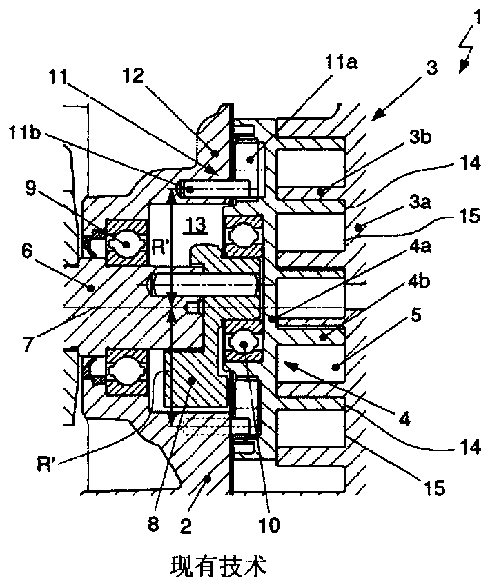
[0066] figure 1 A prior art scroll compressor 1 is shown in cross section. A scroll compressor 1 includes a housing 2; an immovable fixed stator 3 having a disk-shaped base plate 3a and a wall 3b extending from one side of the base plate 3a formed in a spiral shape; The movable scroll 4 is formed with a wall 4b extending from the front side of the base plate 4a. The non-movable or fixed helical part 3 or the movable helical part 4 is also referred to simply as the stator 3 and the movable scroll 4 cooperation, respectively. Here, the base plates 3 a , 4 a are arranged opposite each other such that the walls 3 b of the stator 3 and the walls 4 b of the orbiting scroll 4 are staggered. The movable helix 4 is moved along a circular path by an eccentric drive. During the movement of the helix 4, the walls 3b, 4b contact at several locations and within the walls 3b, 4b are formed several sequentially closed working volumes 5, wherein adjacently arranged working volumes 5 delimit...


PUM


Abstract

The present invention relates to a method for manufacturing a scroll compressor (1) and, particularly, to a pretreatment method for coating regions of a scroll compressor (1), which come into contactwith each other during operation of the scroll compressor (1). The scroll compressor (1) comprises: a fixed scroll (3) including a base plate (3a) and a scroll-shaped wall (3b) extending from one sideof the base plate (3a); and an orbiting scroll (4) including a base plate (4a) and a scroll-shaped wall (4b) extending from the front side of the base plate (4a). The scrolls (3, 4) are formed of a base material.

Description

technical field [0001] The present invention relates to a method of manufacturing a scroll compressor, in particular a method for coating pretreatment of areas that come into contact with each other during operation of the scroll compressor. The invention also relates to a scroll compressor as a device for compressing a gaseous fluid, in particular a refrigerant, having at least one region pretreated and coated according to the method of manufacturing a scroll compressor. Background technique [0002] In climate control systems known in the prior art for mobile applications, in particular for motor vehicles, the compressor for delivering the refrigerant through the refrigerant cycle (also called refrigerant compressor) is often independent of the refrigerant Formed as a piston compressor with variable stroke displacement or as a scroll compressor. The compressor is here driven via a pulley or electrically. [0003] Conventional scroll compressors for refrigerants such as R...

Claims


Application Information

Patent Timeline
IPC IPC(8): C23F1/20C23F1/36C25D11/16C22C21/02F04C18/02
CPCC25D5/44C25D11/16C25D11/24C22C21/02F04C25/00F04C18/0215F04C2230/60F04C2230/90F05C2201/021F05C2201/0496F05C2253/12C23G1/00C23G1/125C23G1/22C22C21/08C23C18/32C23C18/1844C23F1/20C23F1/36C25D11/022C23C18/1837F04C2230/10C23F1/02
Inventor 埃里克-弗洛里安·法尔屈斯卡迪尔·杜尔孙弗劳·苏珊娜·萨尔瓦多努诺·格林
Owner HANON SYST
Why Eureka
Try Eureka