
A kind of sic MOSFET adaptive driving circuit and adaptive driving method

A driving method and adaptive technology, applied in the field of power electronics, can solve the problems of low on-off speed withstanding voltage on-resistance, increased conduction loss, electromagnetic interference of external devices, etc., to suppress peak current or surge voltage, reduce The current change rate, the effect of simple operation and implementation

Active Publication Date: 2021-06-18
QUANZHOU INST OF EQUIP MFG
View PDF5 Cites 0 Cited by
  • Summary
  • Abstract
  • Description
  • Claims
  • Application Information

AI Technical Summary

Problems solved by technology

[0002] SiC MOSFET is a voltage-driven switching device, which has the characteristics of fast on-off speed, high withstand voltage and low on-resistance, and has a high operating frequency. A large peak current is likely to be generated during the fast turn-on process, and a large surge voltage is likely to be generated during the fast turn-off process, causing the SiC MOSFET operating track to exceed the safe operating area (SOA), thereby affecting the reliability and reliability of the SiC MOSFET itself. security, and will also cause serious electromagnetic interference to external devices
[0003] Based on this, the method of increasing the resistance value of the gate drive resistor is usually used to reduce the peak current when the SiC MOSFET is turned on, but this method reduces the turn-on speed of the SiC MOSFET and also increases the conduction loss; usually outside the SiC MOSFET Add a snubber circuit to reduce the surge voltage when the SiC MOSFET is turned off, but this method increases the difficulty and cost of implementation, and the snubber circuit itself also has energy loss

Method used


Image

  • A kind of sic MOSFET adaptive driving circuit and adaptive driving method
  • A kind of sic MOSFET adaptive driving circuit and adaptive driving method

Examples


Embodiment Construction

[0034] In order to further explain the technical solution of the present invention, the present invention will be described in detail below through specific examples.

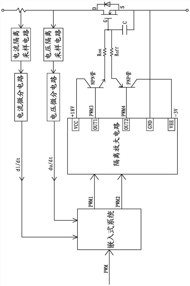
[0035] A SiC MOSFET adaptive drive circuit, such as figure 1 As shown, including embedded system, isolation amplifier circuit, push-pull power amplifier circuit, voltage isolation sampling circuit, current isolation sampling circuit, voltage differential circuit and current differential circuit.

[0036] The embedded system inputs a PWM signal, which is a pulse width modulation signal, and the PWM signal is processed by the embedded system to output PWM1 and PWM2 signals. The embedded system has a PWM1 signal output terminal and a PWM2 signal output terminal. The PWM1 signal output terminal and the PWM2 signal output terminal are respectively connected to the base of the transistor of the push-pull power amplifier circuit through an isolation amplifier circuit, that is, there are two in the push-pull power ampl...


PUM


Abstract

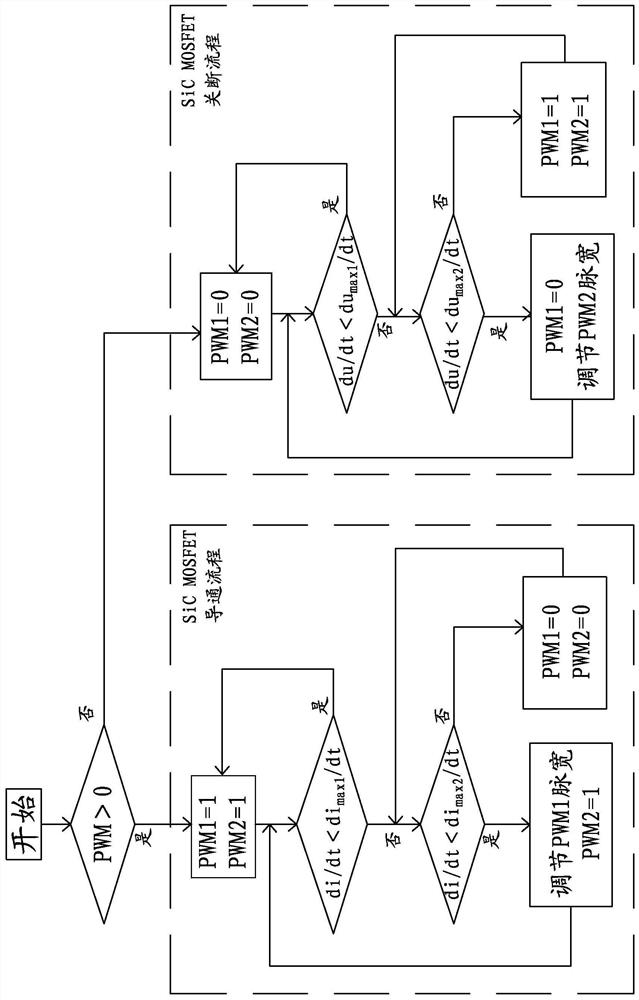
The invention discloses a SiC MOSFET self-adaptive driving circuit and self-adaptive driving method. An embedded system inputs PWM and outputs PWM1 and PWM2. PWM1 and PWM2 are respectively connected to bases of NPN tubes and PNP tubes through isolation amplifying circuits. NPN tubes The collectors of the NPN tube and the PNP tube are respectively connected to the positive and negative terminals of the power supply, the emitters of the NPN tube and the PNP tube are connected to the gate of the SiC MOSFET, and the source of the SiC MOSFET is grounded; obtained by isolating the sampling circuit and the differential circuit respectively The current change rate and voltage change rate of the SiC MOSFET drain; the embedded system adjusts the pulse width of PWM1 and PWM2 in real time according to the PWM level and the current change rate and voltage change rate of the SiC MOSFET drain, and then controls the SiC MOSFET on and off. The peak current or surge voltage generated in the process can be effectively regulated and controlled to realize the adaptive fast on-off operation of SiC MOSFET.

Description

technical field [0001] The invention relates to the technical field of power electronics, and more specifically relates to a SiC MOSFET self-adaptive drive circuit and a drive method. Background technique [0002] SiC MOSFET is a voltage-driven switching device, which has the characteristics of fast on-off speed, high withstand voltage and low on-resistance, and has a high operating frequency. A large peak current is likely to be generated during the fast turn-on process, and a large surge voltage is likely to be generated during the fast turn-off process, causing the SiC MOSFET operating track to exceed the safe operating area (SOA), thereby affecting the reliability and reliability of the SiC MOSFET itself. Safety, and at the same time, it will also cause serious electromagnetic interference to external devices. [0003] Based on this, the method of increasing the resistance value of the gate drive resistor is usually used to reduce the peak current when the SiC MOSFET is...

Claims


Application Information

Patent Timeline
Patent Type & Authority Patents(China)
IPC IPC(8): H02M1/08H02M1/32
CPCH02M1/08H02M1/32H02M1/0054Y02B70/10
Inventor 夏安俊汪凤翔陶鹏黄东晓于新红
Owner QUANZHOU INST OF EQUIP MFG
Learn More