
Micro gyroscope excitation and protection device and method

A technology of miniature gyroscope and protection device, applied in the field of gyroscope, can solve the problems of zero bias instability, limitation of the dynamic response range of the gyroscope, affecting the normal operation, etc.

Active Publication Date: 2020-06-12
尚同电子科技(淄博)有限公司
View PDF5 Cites 1 Cited by
  • Summary
  • Abstract
  • Description
  • Claims
  • Application Information

AI Technical Summary

Problems solved by technology

[0008] 1. There are low-frequency noise signals such as DC bias components in the driving signal. Long-term operation will cause irreversible damage to the gyro and seriously affect its service life. Therefore, the traditional solution is not suitable for long-term operation applications.
[0009] 2. Due to the inherent structural characteristics of the oscillator, there will inevitably be high-frequency harmonics in the output driving signal. The high-frequency harmonics enter the gyroscope through the driving signal, which will cause problems such as unstable scale factors.
[0010] 3. The traditional solution does not effectively process the low-frequency and high-frequency noise signals superimposed in the driving signal, causing the noise signal to enter the gyro, which seriously affects the detection sensitivity of the gyro for tiny input signals, that is, the resolution of the gyro is seriously reduced
[0011] 4. The closed-loop driving circuit of the traditional scheme is subject to the driving signal carrying low-frequency noise and high-frequency noise, and the dynamic response range of the gyroscope is limited by the noise signal
[0012] 5. The high-frequency harmonics superimposed in the tuning signal are not processed in time, causing them to enter the tuning electrode of the gyro, which has an adverse effect on the tuning of frequency splitting, limits the modal matching of the gyro, and causes problems such as zero bias instability
[0013] 6. The traditional solution does not effectively isolate the zero reference electrode of the gyroscope, resulting in various backflow noise signals in the circuit, coupled with stray capacitance into the gyroscope, which will affect the normal operation of the two modes in severe cases
[0014] 7. As a capacitive load, the gyroscope will change greatly during its actual operation. The traditional scheme does not deal with the bias voltage source, resulting in the dynamic performance of the voltage source not meeting the actual operating requirements of the gyroscope, which leads to Problems such as unstable power supply of the gyroscope, which in turn affect the performance indicators of the gyroscope
[0015] 8. The traditional scheme does not effectively deal with the potential input ripple of the bias voltage source. When the input ripple appears and acts on the gyro, there is a high probability that the gyro will be broken down, which is permanent irreversible serious damage. The entire gyro system will be scrapped, which will cause the inertial navigation system to fail

Method used


Image

  • Micro gyroscope excitation and protection device and method
  • Micro gyroscope excitation and protection device and method
  • Micro gyroscope excitation and protection device and method

Examples


Embodiment 1

[0099] Such as figure 1 and figure 2 As shown, Embodiment 1 describes a miniature gyro excitation and protection device, which includes a gyro circuit, a reference source circuit, a demodulation drive tuning circuit, and an electromechanical interface.

[0100] The gyro circuit, the reference source circuit and the demodulation drive tuning circuit are connected through the electromechanical interface, and the signal is transmitted through the corresponding electromechanical interface. The reference source circuit, the demodulation drive tuning circuit play the role of excitation and protection.

[0101] The following is a further detailed description of the composition structure and connection relationship of the above circuits:

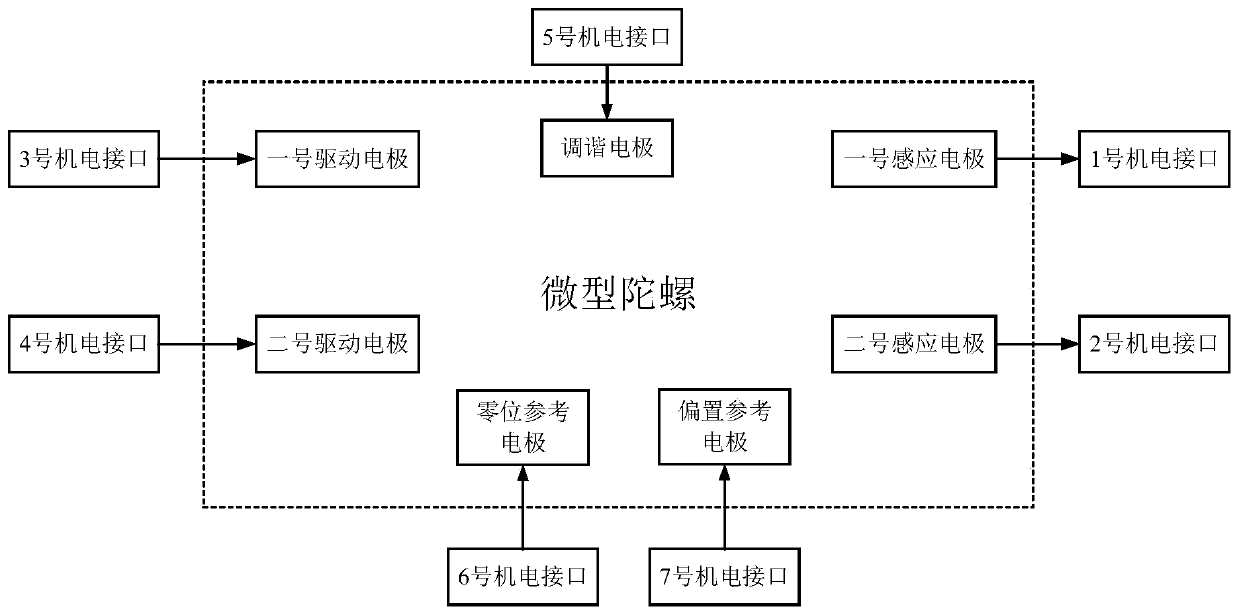
[0102] Such as image 3 As shown, the gyro circuit includes a first sensing electrode, a second sensing electrode, a first driving electrode, a second driving electrode, a tuning electrode, a zero reference electrode, and a bias reference electro...

Embodiment 2

[0177] Embodiment 2 describes a micro gyro excitation and protection method, which is based on the micro gyro excitation and protection device in the above embodiment 1. to combine figure 1 and Figure 5 As shown, the miniature gyroscope excitation and protection method includes the following steps:

[0178] I. The signal reference source generates a zero reference source signal and sends it to the first ferrite.

[0179] The first ferrite processes the zero reference source signal, and the processed signal is sent to the zero reference electrode.

[0180] The bias voltage source generates a bias reference source signal and sends it to the LDO circuit.

[0181] The LDO circuit processes the bias reference source signal, and the processed signal is sent to the bias reference electrode.

[0182] II. The gyroscope produces output signals in two vibration modes, namely the output signals of the first vibration mode and the second vibration mode.

[0183] The output signal of ...


PUM


Abstract

The invention belongs to the technical field of gyroscopes, and particularly discloses a micro gyroscope excitation and protection device and method. The micro gyroscope excitation and protection device is used for detecting and analyzing the resonant frequency of the gyroscope in real time and adjusting the passband frequency of the passband adjustable buffer on line, so that low-frequency and high-frequency noises can be effectively prevented from entering the gyroscope, and the detection resolution ratio and the dynamic response range of the gyroscope are improved. Besides, high-frequency harmonics superposed in the tuning signal are processed, so that the modal matching performance of the gyroscope is improved, and the zero-bias stability of the gyroscope is further improved. Finally,measures such as isolation and passband adjustability are adopted, input ripples, backflow noise and direct-current bias components are inhibited from entering the gyroscope, irreversible damage to the mechanical structure of the gyroscope is prevented, potential safety threats are effectively avoided, the service life of the gyroscope is prolonged, and the gyroscope is suitable for the application field of long-time operation.

Description

technical field [0001] The invention belongs to the technical field of gyroscopes, and relates to a miniature gyroscope excitation and protection device and a miniature gyroscope excitation and protection method based on the miniature gyroscope excitation and protection device. Background technique [0002] In recent years, the rapid development of inertial navigation technology has fully driven the development of related sensor industries, and micro gyroscopes are a typical representative of them. However, due to the inherent characteristics of the mechanical structure of the micro-gyroscope, various errors will inevitably occur in the actual operation process, such as zero bias instability, scale factor instability and other problems. [0003] Tracing back to the source, in addition to the errors caused by the mechanical structure of the gyroscope itself, the errors caused by its excitation devices also emerge in endlessly. Therefore, the research on the micro-gyro excita...

Claims


Application Information

Patent Timeline
IPC IPC(8): G01C19/56G05F1/56
CPCG01C19/56G05F1/56
Inventor 王雨晨董宇航李崇宫宜辉
Owner 尚同电子科技(淄博)有限公司
Learn More