Stacked sleeve type condenser

A condenser and casing-type technology, which is applied in the field of vapor compression refrigeration system, can solve the problems such as the decrease of heat exchange efficiency of the refrigeration system, the reduction of the heat exchange area of ​​the condenser, and the decrease of the flow rate of the refrigerant, etc., so as to prolong the refrigeration time and balance the speed Fast, the effect of improving heat exchange efficiency

Pending Publication Date: 2020-06-12
CHANGHONG MEILING CO LTD
View PDF0 Cites 0 Cited by
  • Summary
  • Abstract
  • Description
  • Claims
  • Application Information

AI Technical Summary

Problems solved by technology

[0004] Under the same conditions, the larger the surface heat exchange area of ​​the condenser in the refrigeration system, the higher the efficiency. Although increasing the diameter of the condenser pipe can increase the heat exchange area, the increase in the diameter of the pipe will reduce the flow rate of the refrigerant and dissolve in the refrigeration system. The refrigerating oil in the refrigerant will suffer from oil separation when the flow rate is lower than the rated flow rate. Too much refrigerating oil in the condenser will reduce the heat transfer efficiency of the refrigeration system. Therefore, a condenser is required without reducing the heat transfer of the condenser. Reduce the internal volume while reducing the area, prolong the effective refrigeration time, and improve the efficiency of the refrigeration system

Method used


Image

  • Stacked sleeve type condenser
  • Stacked sleeve type condenser
  • Stacked sleeve type condenser

Examples


Embodiment 1

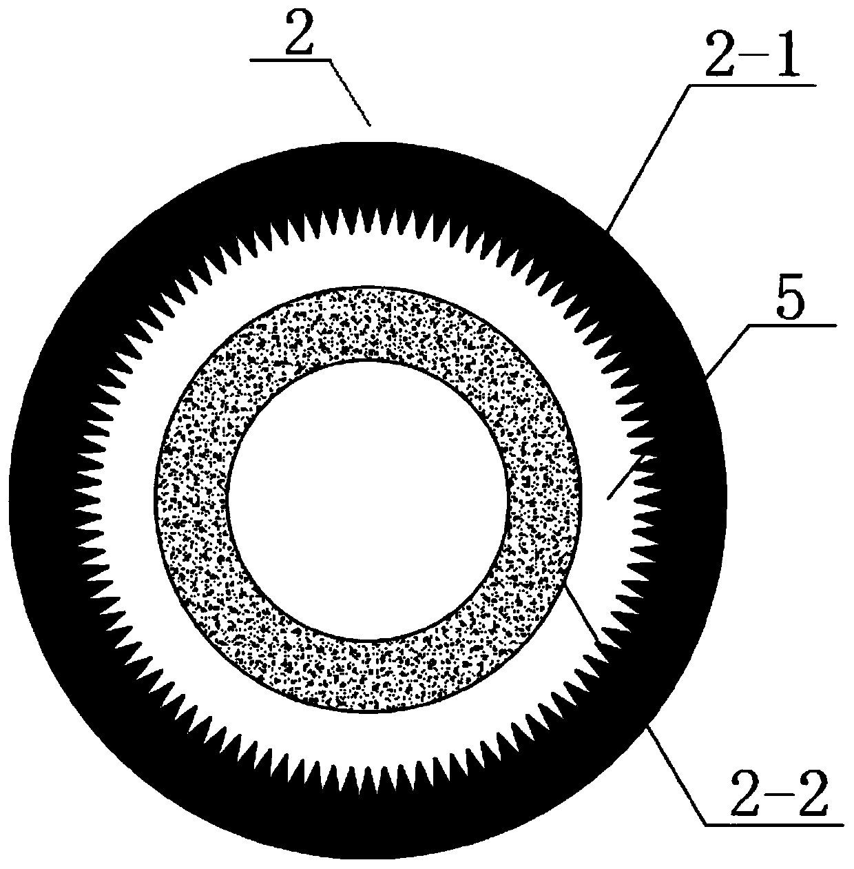
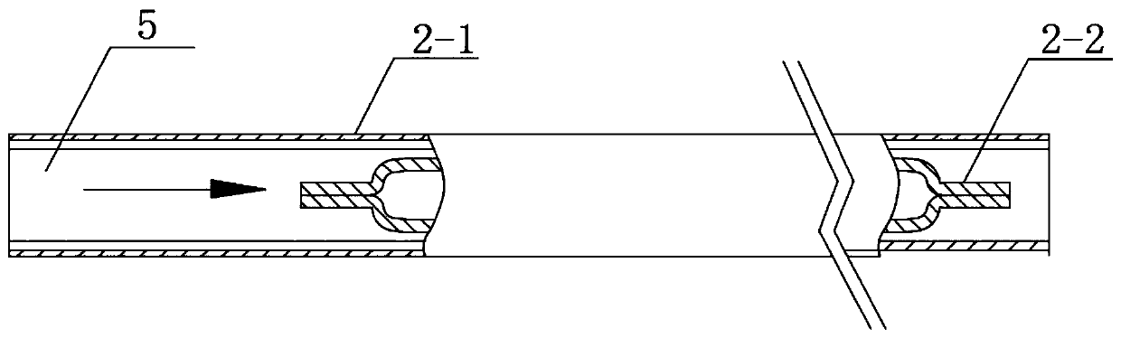
[0033] see Figure 1-6 As shown, the present invention is a stacked casing condenser, including a condenser 2; the outside of the condenser 2 is an outer casing 2-1; the outer casing 2-1 is equipped with an inner liner 2-2;

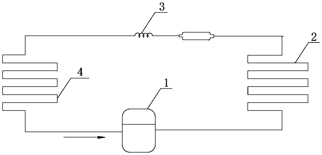
[0034] Among them, such as Figure 1-2 As shown, the outlet end of the condenser 2 is sequentially connected with a throttling device 3, an evaporator 4, and a compressor 1; the outlet end of the compressor 1 is connected with the inlet end of the condenser 2 to form a circulating refrigeration system; the interior of the circulating refrigeration system is filled with refrigeration Refrigerant 5; Refrigerant 5 flows out from the outlet of compressor 1, flows through condenser 2, throttling device 3 and evaporator 4 in sequence, and flows into the inlet of compressor 1; inner liner 2-2 is arranged on outer casing 2- 1, so that the liquefaction flow rate of the refrigerant 5 at the outlet end of the condenser 2 is reduced, and the flow rate of the refrige...

Embodiment 2

[0042] see Figure 1-6 As shown, the present invention is a stacked casing condenser, including a condenser 2; the outside of the condenser 2 is an outer casing 2-1; the outer casing 2-1 is equipped with an inner liner 2-2;

[0043] Among them, such as Figure 1-2 As shown, the outlet end of the condenser 2 is sequentially connected with a throttling device 3, an evaporator 4, and a compressor 1; the outlet end of the compressor 1 is connected with the inlet end of the condenser 2 to form a circulating refrigeration system; the interior of the circulating refrigeration system is filled with refrigeration Refrigerant 5; Refrigerant 5 flows out from the outlet of compressor 1, flows through condenser 2, throttling device 3 and evaporator 4 in sequence, and flows into the inlet of compressor 1; inner liner 2-2 is arranged on outer casing 2- 1, so that the liquefaction flow rate of the refrigerant 5 at the outlet end of the condenser 2 is reduced, and the flow rate of the refrige...


PUM


Abstract

The invention discloses a stacked sleeve type condenser, and relates to the technical field of vapor compression type refrigerating systems. The stacked sleeve type condenser comprises a condenser body, an outer sleeve is arranged outside the condenser body, a lining pipe is installed inside the outer sleeve, the outlet end of the condenser body is sequentially connected with a throttling device,an evaporator and a compressor, the outlet end of the compressor is connected with the inlet end of the condenser body to form a circulating refrigeration system, the circulating refrigeration systemis filled with a refrigerant, the refrigerant flows out of the outlet end of the compressor, sequentially flows through the condenser body, the throttling device and the evaporator and flows into theinlet end of the compressor, and the lining pipe is arranged at the outlet end of the outer sleeve. According to the stacked sleeve type condenser, by arranging the lining pipe inside the outer sleeveof the condenser body, the internal volume is reduced while the heat exchange area of the condenser body is not reduced, the effective refrigeration time is prolonged, and the efficiency of a refrigeration system is improved.

Description

technical field [0001] The invention belongs to the technical field of vapor compression refrigeration systems, and in particular relates to a laminated casing condenser. Background technique [0002] The vapor compression refrigeration system is a closed circuit. The compressor drives the refrigerant to circulate in the condenser, capillary, evaporator, return pipe and other components in order to transfer heat. The condenser is a heat-releasing part. The compressor inputs the high-temperature and high-pressure gaseous refrigerant into the condenser. Through the heat exchange between the condenser and the outside world, the internal refrigerant gradually condenses from gaseous state to liquid state. As the phase state of the refrigerant changes, The flow rate of the refrigerant gradually decreases. [0003] Refrigerators and air conditioners are vapor compression refrigeration systems. The compressors are turned on and off periodically to control the constant temperature i...

Claims


Application Information

Patent Timeline
Patent Type & Authority Applications(China)
IPC IPC(8): F25B39/04F28D7/10F28F1/06
CPCF25B39/04F28D7/106F28F1/06F25B2339/04
Inventor 荆嵩李艳革李清松
Owner CHANGHONG MEILING CO LTD
Why Eureka
Try Eureka