
Roller type rail clamping device

A roller type and roller technology, which is applied in the field of roller type rail clamping devices, can solve the problems of unreliable work, large influence of electromagnets and high cost, and achieve the effects of reducing operating costs, simplifying structure and improving reliability.

Pending Publication Date: 2020-06-12
HANGZHOU HUNING ELEVATOR PARTS CO LTD
View PDF1 Cites 4 Cited by
  • Summary
  • Abstract
  • Description
  • Claims
  • Application Information

AI Technical Summary

Problems solved by technology

[0004] However, the existing electromagnetic rail clamps have the following disadvantages: the attraction force of the electromagnet is greatly affected by the gap between the electromagnet and the guide rail and the operating position, the work is unreliable, and a large electromagnet structure is required
The motor control method is affected by the life of the motor in the compression and release control. When the elevator frequency operates, the life of the whole machine is not long and the cost is high.

Method used


Image

  • Roller type rail clamping device
  • Roller type rail clamping device
  • Roller type rail clamping device

Examples


Embodiment 1

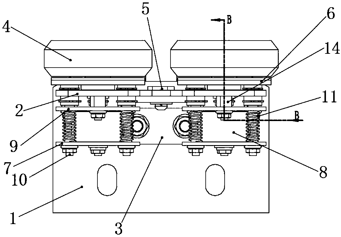
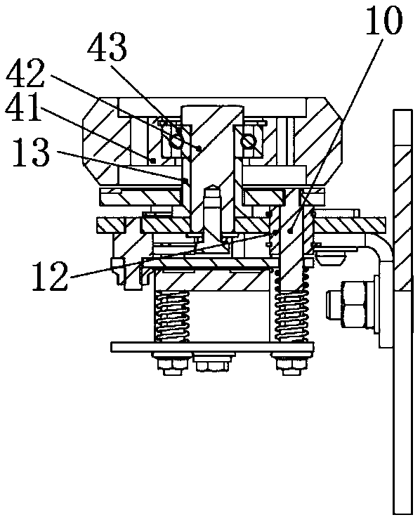
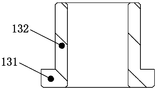
[0034] Such as Figure 1-5 As shown, the roller-type rail clamping device of this embodiment is applied to an elevator to keep the elevator in a stable running state. Specifically, the roller-type rail clamping device includes a base 1 and a turret 2 rotatably fitted on the base 1. Specifically, the base 1 is a rectangular plate structure, and the base 1 is equipped with a mounting frame 3 along the central axis of its long side. ,Such as Figure 4 As shown, the mounting frame 3 is an L-shaped structure, including a horizontal portion 31 and a vertical portion 32. The horizontal portion 31 of the mounting frame is fixedly connected to the base 1 by bolts or screws. For example, the bolts pass through the base 1 sequentially from bottom to top. The horizontal portion 31 of the mounting frame is fixed by nuts above the horizontal portion 31 of the mounting frame; among them, the base 1 and the horizontal portion 31 of the mounting frame are fixed by two bolts distributed on the...

Embodiment 2

[0049] The difference between the roller type rail clamping device of the present embodiment and the first embodiment is that:

[0050] The drive assembly can also be replaced by drive mechanisms in the prior art such as spring drive, motor drive, hydraulic drive, pneumatic, etc., as long as the friction disc is driven towards the roller direction and a certain driving force can be applied to make the friction disc restrain the roller. just move. Realize the diversification of the structure of the braking mechanism to adapt to different installation conditions, so that the application range of the roller-type rail clamping device of this embodiment is wider.

[0051] Other structures can refer to Embodiment 1.

Embodiment 3

[0053] The difference between the roller type rail clamping device of the present embodiment and the first embodiment is that:

[0054] The brake rollers can be in the same group as the guide rollers of the roller guide shoe, and a braking mechanism is added to the roller guide shoe to form an integrated device of the roller guide shoe and the roller-type rail clamping device.


PUM


Abstract

The invention belongs to the technical field of elevators, and particularly relates to a roller type rail clamping device which is used for an elevator. The roller type rail clamping device comprisesa base and a rotary rack which is rotationally connected to the base, and the two sides of the rotary rack are each provided with a roller and a braking mechanism of the roller. A guide rail of the elevator penetrates between the rollers on the two sides of the rotary rack, so that the guide rail and the rollers on the two sides of the rotary rack are in a holding state all the time without derailing; when the elevator is in a stop state, the braking mechanisms stop the rollers, and frictional resistance is generated between the guide rail and the rollers or between the braking mechanisms andthe rollers to prevent shaking of the elevator, and therefore, an elevator car is in a stable state; and when the elevator is in a running state, braking of the braking mechanisms to the rollers is removed. The problems are solved that the requirements for centering and an installation gap of a traditional rail clamping device are high, the running reliability is low, and the service life is short.

Description

technical field [0001] The invention belongs to the technical field of elevator accessories, and in particular relates to a roller-type rail clamping device. Background technique [0002] In order to solve the shaking caused by people entering and leaving the elevator on high floors, rail clamps are added to solve the shaking and prevent people from easily getting dizzy when entering and leaving. [0003] At present, electromagnets are mostly used to generate electromagnetic force or motors are driven and released by springs to clamp guide rails to solve the shaking problem. For example, the patent document whose publication number is CN102942089B discloses an electromagnetic rail clamp, including a yoke, a coil, an armature, and an armature reset assembly. The yoke has two sides, and the yoke is covered with coils; For the clamped guide rail, there are armatures on both sides of the yoke, the inner end of the armature is facing the guide rail, and the armature is connected...

Claims


Application Information

Patent Timeline
IPC IPC(8): B66B5/18
CPCB66B5/18
Inventor 邹家春姚荣康刘坤李黎
Owner HANGZHOU HUNING ELEVATOR PARTS CO LTD
Learn More