
Bevel gear coaxial contra-rotating double-rotor transmission mechanism

A technology of transmission mechanism and gear transmission, which is applied to gear transmission devices, rotorcraft, and transmission devices to drive multiple propellers, etc., which can solve the problems of low bearing capacity and low reliability of compound high-speed helicopters, and reduce gear transmission. The effect of load and system quality, high reliability, and compact system structure

Pending Publication Date: 2020-06-12
XIAN TECH UNIV
View PDF0 Cites 0 Cited by
  • Summary
  • Abstract
  • Description
  • Claims
  • Application Information

AI Technical Summary

Problems solved by technology

[0008] In view of this, the present invention provides a bevel gear coaxial counter-rotating double-rotor transmission mechanism in order to solve the problems of low bearing capacity and low reliability of the compound high-speed helicopter existing in the prior art

Method used


Image

  • Bevel gear coaxial contra-rotating double-rotor transmission mechanism
  • Bevel gear coaxial contra-rotating double-rotor transmission mechanism
  • Bevel gear coaxial contra-rotating double-rotor transmission mechanism

Examples


Embodiment 1

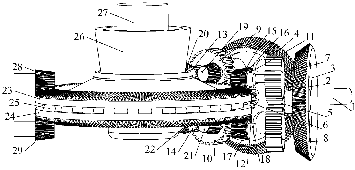
[0031] Embodiment 1: This embodiment is a structure of a bevel gear coaxial counter-rotating double-rotor transmission mechanism input by a single engine, such as figure 1 Shown: including three-stage torque splitter unit and coaxial output part;

[0032] The above-mentioned three-stage torque splitting unit is a three-stage fixed-axis gear train, including I-stage gear transmission, II-stage gear transmission and III-stage gear transmission;

[0033] The above-mentioned I-level gear transmission includes a power input shaft 1, and the power input shaft 1 is fixedly connected with the power input gear 2 to complete the first-level transmission of power; the power input gear 2 is connected to the first I-level face gear 3 and the second I-level face gear The gears 4 are meshed at the same time, and adopt radial floating support to complete the primary distribution of power;

[0034] The above-mentioned stage II gear transmission includes a first stage II small cylindrical gear...

Embodiment 2

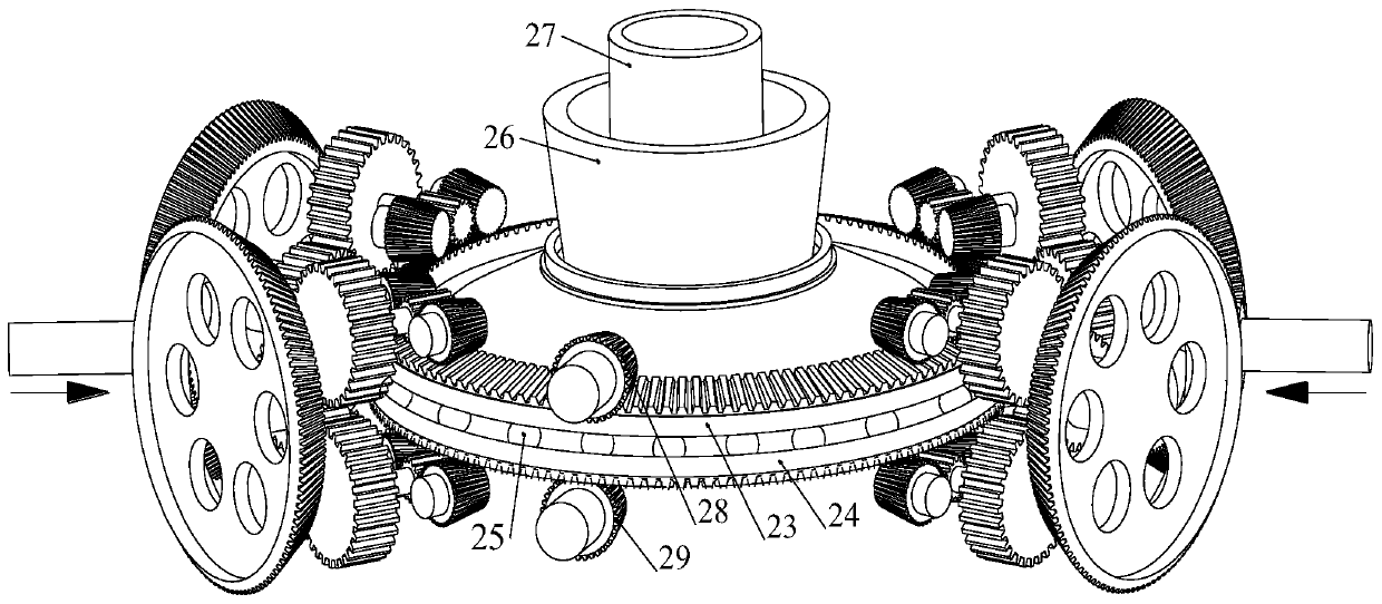
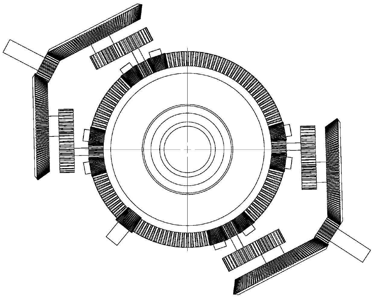
[0040] This embodiment is a structure of a bevel gear coaxial counter-rotating double-rotor transmission mechanism input by two engines, such as Figure 2-Figure 3 As shown: the structure is the same as that of the embodiment, the difference is that it adopts dual-engine power input, that is, it has two three-stage torsion splitter units with the same configuration, and they are distributed symmetrically or approximately symmetrically along the circumference.

[0041] The present invention increases the double-rotor combined mechanism on the basis of the double-engine input in the second embodiment, and adds the lower rotor 31 connected to the upper output shaft 26 and the upper rotor 30 connected to the lower output shaft 27, and the rest of the structure is the same as that of the second embodiment ,Such as Figure 4 shown.

[0042] The present invention has four times of power splitting and converging, mainly including three power splitting transmissions of three-stage fix...


PUM


Abstract

The invention discloses a bevel gear coaxial contra-rotating double-rotor transmission mechanism. The transmission mechanism comprises a three-level torque dividing unit and a bevel gear coaxial output unit. Primary power of the mechanism is transmitted into a system through an input shaft gear, three times of distribution are completed through a three-level gear transmission device composed of aface gear, a straight gear and a bevel gear, finally the primary power is converged into a coaxial bevel gear supported by a thrust bearing, and power reversing and power input are achieved. And finally, power three-way shunt output is realized through an output shaft fixedly connected with the bevel gear and a straight gear meshed with the bevel gear. The transmission mechanism adopts fixed-axistransmission, is compact in structure and high in reliability, and can be applied to transmission systems of other equipment such as a composite high-speed helicopter.

Description

technical field [0001] The invention relates to a power transmission system of a helicopter, in particular to a bevel gear coaxial counter-rotating double-rotor transmission mechanism. Background technique [0002] As a typical structure of compound high-speed helicopter, the coaxial counter-rotating twin-rotor helicopter differs from the single-rotor helicopter in that it installs two rotors with equal rotational speed and opposite directions on the mutually concentric shafts. Because the rotor speeds are equal and the steering is opposite, the reaction moments produced by the two rotors can be balanced with each other, and there is no need to use the tail rotor to balance the reaction moments produced by the rotors. [0003] Coaxial counter-rotating twin-rotor helicopters all adopt a structure with a tail rotor, which mainly uses the tail rotor as the forward flight propulsion system of the helicopter to increase the flight speed of the helicopter. At present, there are t...

Claims


Application Information

Patent Timeline
Patent Type & Authority Applications(China)
IPC IPC(8): B64C27/12B64C27/10B64D35/06B64D35/08F16H1/20
CPCB64C27/12B64C27/10B64D35/06B64D35/08F16H1/20
Inventor 董皓张建文王理邦张灏秦赵晓龙刘锡尧李博王亚娟
Owner XIAN TECH UNIV
Learn More