Bevel gear configuration coaxial double-rotor variable-speed transmission mechanism

A coaxial dual-rotor, variable-speed transmission technology, which is applied to gear transmissions, rotorcraft, and transmissions to drive multiple propellers, can solve the problems of low bearing capacity and low flight speed of high-speed helicopters, and achieve large transmission ratios , stable transmission and compact system structure

Pending Publication Date: 2020-06-12
XIAN TECHNOLOGICAL UNIV
View PDF0 Cites 2 Cited by
  • Summary
  • Abstract
  • Description
  • Claims
  • Application Information

AI Technical Summary

Problems solved by technology

[0005] In view of this, the present invention provides a coaxial double-rotor transmission mechanism with bevel gear configuration to solve the problems of low bearing capacity and low flight speed of high-speed helicopters in the prior art.

Method used


Image

  • Bevel gear configuration coaxial double-rotor variable-speed transmission mechanism
  • Bevel gear configuration coaxial double-rotor variable-speed transmission mechanism
  • Bevel gear configuration coaxial double-rotor variable-speed transmission mechanism

Examples


Embodiment 1

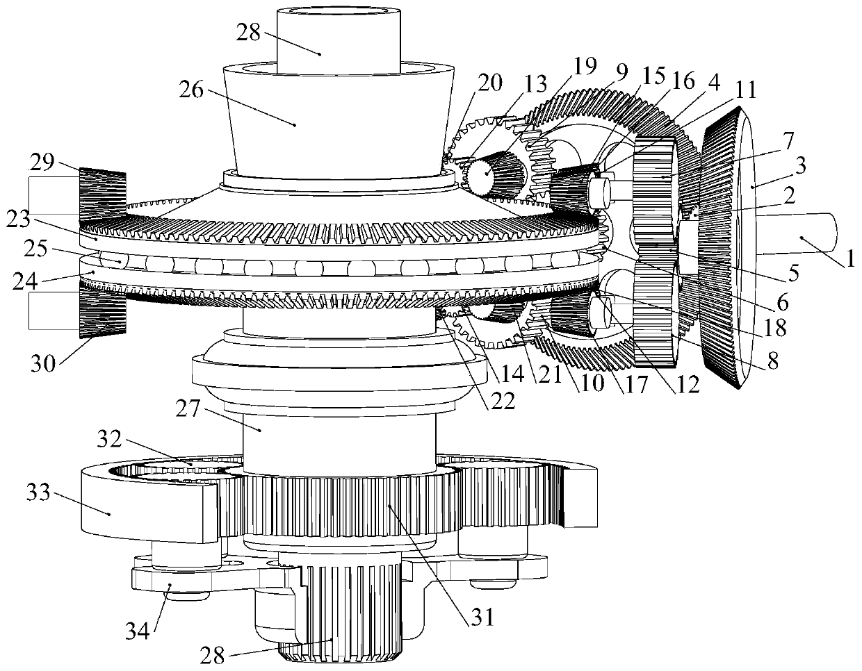
[0029] This embodiment provides a single-engine input bevel gear configuration coaxial double-rotor transmission mechanism, such as figure 1 As shown: it includes a graded reduction device and a coaxial reduction device; the graded reduction device includes a power input shaft 1, and the power input shaft 1 is fixedly connected to the primary driving wheel 2 to realize primary transmission; the primary driving wheel 2 It meshes with the first driven surface gear 3 and the second driven surface gear 4 at the same time, and adopts radial floating support to complete a power split; the first driven surface gear 3 and the second driven surface gear 4 pass through The split torsion shaft is fixedly connected with the first and second driving wheels 5 and the second driving wheel 6 respectively to realize two-stage transmission; the first and second driving wheels 5 are simultaneously connected with the first and second driven wheels 7 and the second driven wheels 8 meshing; the sec...

Embodiment 2

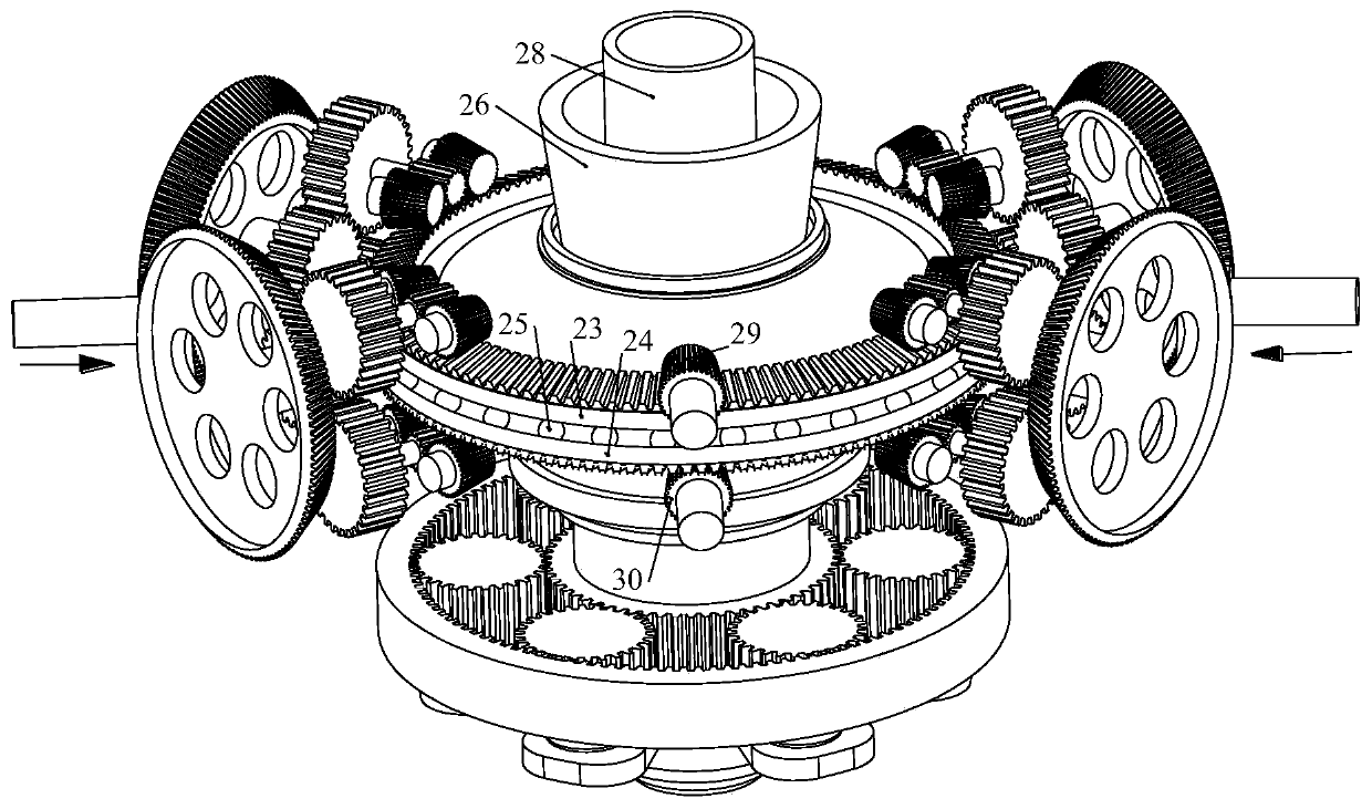
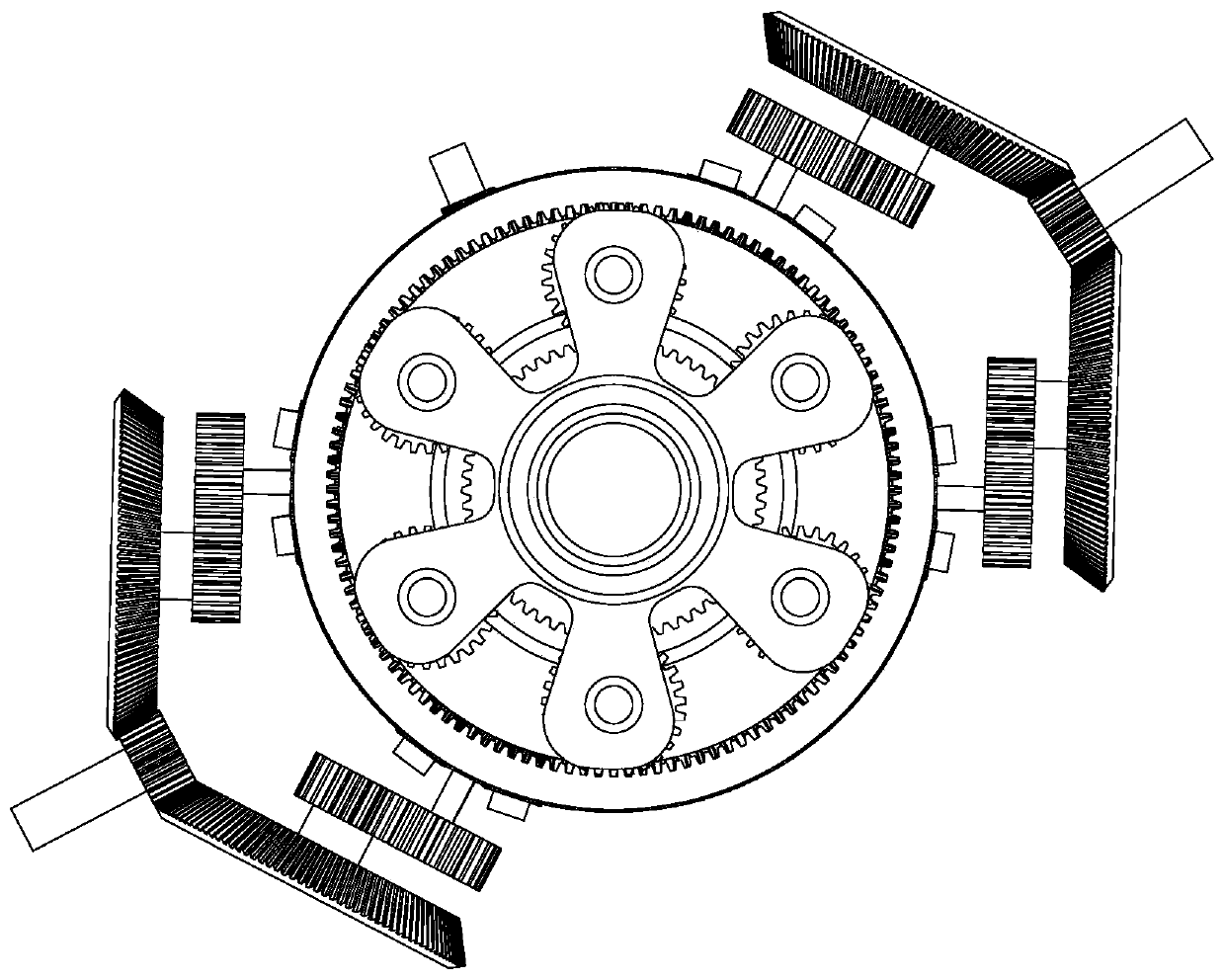
[0038] The bevel gear configuration coaxial double-rotor speed change transmission mechanism provided by the double engine input provided by this embodiment, such as figure 2 and image 3 As shown: the structure of this embodiment is the same as that of Embodiment 1, the difference is that this embodiment adopts dual-engine power input, has two sets of stepped reduction devices, and the configuration of the two sets of devices is the same, and they are distributed symmetrically or approximately symmetrically along the circumference .

[0039] Such as image 3 As shown, on the basis of the second embodiment, the lower rotor 36 connected with the first output shaft 26 and the upper rotor 35 connected with the third output shaft 28 are added, and the rest of the structure is the same as that of the second embodiment.


PUM


Abstract

The invention discloses a bevel gear configuration coaxial double-rotor variable-speed transmission mechanism. The transmission mechanism comprises a graded speed reduction device and a coaxial speedreduction device. The graded speed reduction device mainly completes multi-path distribution of power through a three-stage gear transmission mechanism, meanwhile, torque distribution and speed reduction functions are achieved, and a load and a linear speed borne by a gear are reduced. The coaxial speed reduction device comprises an upper bevel gear and a lower bevel gear which are coaxial back toback, the upper bevel gear is fixedly connected with the lower rotor wing through an output shaft, the lower bevel gear is fixedly connected with the upper rotor wing through a planetary speed reduction mechanism, and then double-rotor-wing power output with the variable rotating speed and the opposite rotating directions is achieved. The transmission mechanism has the advantages of being high inbearing capacity, high in efficiency and the like and can be applied to the fields of high-speed helicopters, vessel transmission systems and the like.

Description

technical field [0001] The invention relates to a power transmission system of a helicopter, in particular to a coaxial double-rotor transmission mechanism with a bevel gear configuration. Background technique [0002] The flight speed of high-speed helicopters can reach more than 400km / h, and its main configuration is usually a coaxial main rotor with a tail rotor configuration. When the helicopter is flying forward at high speed, in order to avoid the forward blade shock wave, it is necessary to reduce the rotor speed. Reducing the rotor speed can be achieved through engine speed change and transmission system speed change. The normal operating speed range of the engine is small, and the range of reducing the rotor speed by reducing the engine speed is very limited, so the transmission system speed change is very necessary. [0003] At present, aviation transmission transmission devices can be divided into two categories: one is clutch transmission devices, which mainly u...

Claims


Application Information

Patent Timeline
Patent Type & Authority Applications(China)
IPC IPC(8): B64C27/12B64C27/10B64D35/06B64D35/08F16H1/28
CPCB64C27/12B64C27/10B64D35/06B64D35/08F16H1/2854
Inventor 董皓张建文王理邦张灏秦赵晓龙刘锡尧李博王亚娟
Owner XIAN TECHNOLOGICAL UNIV
Why Eureka
Try Eureka