
Vehicle positioning method and device based on imaging equipment

An imaging device and vehicle positioning technology, applied in vehicle position/route/height control, two-dimensional position/course control, measuring devices, etc., can solve problems such as difficulty in meeting positioning accuracy requirements and interference

Active Publication Date: 2020-06-09
BEIJING TUSEN ZHITU TECH CO LTD
View PDF5 Cites 0 Cited by
  • Summary
  • Abstract
  • Description
  • Claims
  • Application Information

AI Technical Summary

Problems solved by technology

However, due to signal interference and other conditions, GNSS is difficult to meet the positioning accuracy requirements in some high-precision scenes (such as scenes with complex electromagnetic environments such as ports, where GNSS signals will be strongly interfered), so the assistance of other sensors, such as cameras, is required. LiDAR, etc.

Method used


Image

  • Vehicle positioning method and device based on imaging equipment
  • Vehicle positioning method and device based on imaging equipment
  • Vehicle positioning method and device based on imaging equipment

Examples


Embodiment Construction

[0029] The following will clearly and completely describe the technical solutions in the embodiments of the present invention with reference to the accompanying drawings in the embodiments of the present invention. Obviously, the described embodiments are only some, not all, embodiments of the present invention. Based on the embodiments of the present invention, all other embodiments obtained by persons of ordinary skill in the art without making creative efforts belong to the protection scope of the present invention.

[0030] In order to facilitate understanding of the present invention, the following technical terms involved in the present invention are explained:

[0031] Camera geometry model: the process of mapping a point (in meters) in three-dimensional space to a two-dimensional image plane (in pixels) according to the internal and external parameters of the camera.

[0032] Localization: Computing the position of a vehicle or mobile robot in its current environment b...


PUM


Abstract

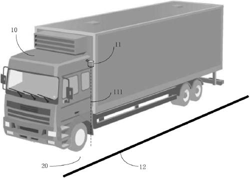
The invention provides a vehicle positioning method and device based on imaging equipment and relates to the technical field of vehicle positioning. The imaging equipment is fixedly arranged on one side, close to a lane marker, of a vehicle, and an optical axis of the imaging equipment is perpendicular to a lane plane. The method comprises steps of controlling the imaging equipment to acquire an image, determining an optical center coordinate of the imaging equipment in the image, and identifying the lane marker in the image to obtain a parameterized line of the lane marker in the image; obtaining a first distance from the optical center coordinate to the parameterized line; according to the first distance, a second distance from the optical center of the imaging equipment to a lane planeand the focal length of the imaging equipment, obtaining the relative distance from an intersection point of the optical axis of the imaging equipment and the lane plane to an extension line formed bythe lane marker; and positioning the vehicle according to the relative distance. The method is advantaged in that positioning precision can be ensured to achieve the better effect, identification ofthe lane marker is simpler, so the whole vehicle positioning method is easy to realize.

Description

technical field [0001] The present invention relates to the technical field of vehicle positioning, in particular to a vehicle positioning method and device based on imaging equipment. Background technique [0002] At present, positioning technology, as an important technology in the field of unmanned driving, has received widespread attention from researchers. When the vehicle is running, it is necessary to use positioning technology to determine the position of the vehicle at all times. A current common solution is to use a global navigation satellite system (Global Navigation Satellite System, GNSS for short) as a basis for self-positioning. However, due to signal interference and other conditions, GNSS is difficult to meet the positioning accuracy requirements in some high-precision scenes (such as scenes with complex electromagnetic environments such as ports, where GNSS signals will be strongly interfered), so the assistance of other sensors, such as cameras, is requi...

Claims


Application Information

Patent Timeline
Patent Type & Authority Applications(China)
IPC IPC(8): G05D1/02G01C21/36
CPCG05D1/0246G01C21/3658
Inventor 李智超王乃岩
Owner BEIJING TUSEN ZHITU TECH CO LTD
Learn More