
Corn peeling equipment for agricultural machinery

A technology for agricultural machinery and corn, applied in the field of corn peeling equipment for agricultural machinery, can solve the problems of damaged corn kernels, affecting the processing and sales of peeled corn, and achieve the effect of improving efficiency

Active Publication Date: 2020-12-22
温州普奈机械科技有限公司
View PDF1 Cites 0 Cited by
  • Summary
  • Abstract
  • Description
  • Claims
  • Application Information

AI Technical Summary

Problems solved by technology

A kind of corn peeling device that is convenient to clean debris in the above-mentioned patent has the following disadvantages: the device realizes the corn peeling effect through the friction extrusion between the corn and the peeling roller, but this peeling method will cause the corn kernels to be damaged. The damage is serious, which affects people's subsequent processing and sales of dehulled corn

Method used


Image

  • Corn peeling equipment for agricultural machinery
  • Corn peeling equipment for agricultural machinery
  • Corn peeling equipment for agricultural machinery

Examples


Embodiment 1

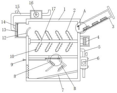
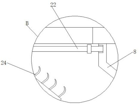
[0026] refer to Figure 1-4 , a corn peeling equipment for agricultural machinery, comprising a box body 1, a feed cylinder 3 is plugged into one side outer wall of the box body 1, and an exhaust fan 16 is connected to the top outer wall of the box body 1 by bolts, one of the exhaust fan 16 The side outer wall is plugged with a suction pipe 15, and one end of the suction pipe 15 is plugged with a collecting box 14, and the collecting box 14 is connected on the side outer wall of the casing 1 by bolts, and the top of the collecting box 14 and the The inner wall of the bottom is clamped with a filter screen 13, the outer wall of one side of the box body 1 is connected with a blower 6 by bolts, and the top outer wall of the blower 6 is inserted with an air inlet pipe 5, and the outer wall of one side of the box body 1 is connected by bolts. The inner wall of one side of the protective shell is connected with the motor 4 by bolts, the outer wall of one end of the output shaft of t...

Embodiment 2

[0030] refer to Figure 5-6 , a corn peeling equipment for agricultural machinery. Compared with Embodiment 1, the outer wall of one side of the filter screen 13 is welded with a support rod 25, and the outer wall of the support rod 25 is welded with a steel needle 26.

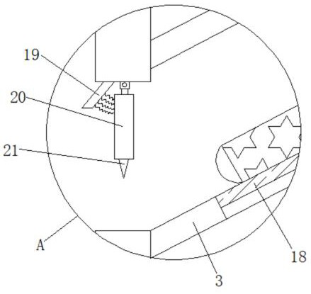
[0031] Working principle: When in use, people can put corn into the box body 1 through the feeding barrel 3. When the corn enters the box body 1 from the feeding barrel 3, the first blade 18 at the bottom of the feeding barrel 3 can slide down The bottom epidermis of the corn is scratched, and the second blade 21 at the bottom of the support plate 20 can scratch the upper epidermis of the corn at the final stage of entering the box 1, thereby improving the efficiency of subsequent peeling of the corn. At the same time, one side of the support plate 20 The spring connected to the outer wall can avoid the situation that the second channel may be blocked due to the different specifications of the corn. When the c...


PUM


Abstract

The invention discloses a corn peeling equipment for agricultural machinery, which comprises a box body, a feeding barrel is plugged into one side of the outer wall of the box body, and an exhaust fan is arranged on the top outer wall of the box body, and one side of the exhaust fan is The outer wall is plugged with a suction pipe, and one end of the suction pipe is plugged with a collection box. In the present invention, when the corn enters the inside of the box through the feeding cylinder, people first start the blower and the motor, and the blower can apply a thrust to the corn skin, and the thrust can break the corn skin to achieve the corn peeling requirement, and then start the suction The fan and the suction fan can apply a pulling force to the corn skin, which can tear the corn skin. The positive and negative force cycles act on the corn skin, which can fully peel the corn without causing damage to the corn surface. At the same time, the motor can drive the rotating rod to slowly turn over the corn, which improves the efficiency of the device for peeling the corn.

Description

technical field [0001] The invention relates to the technical field of corn peeling, in particular to a corn peeling device for agricultural machinery. Background technique [0002] Corn is also known as corn, pearls, etc., and is a plant of the Poaceae Zea genus. It is native to Central and South America and is now cultivated all over the world. It is an important food crop and feed crop, and it is also the crop with the highest total output in the world. Because it is rich in various nutrients such as protein, it is known as a longevity food and is also an important industrial raw material. At present, dehulling is one of the essential steps in the processing of corn. [0003] After retrieval, the Chinese patent publication number is the patent of CN209901350U, discloses a kind of corn peeling device that is convenient to clean debris, comprises base. This corn peeling device is convenient for cleaning debris. The debris produced after the corn is peeled enters the insid...

Claims


Application Information

Patent Timeline
Patent Type & Authority Patents(China)
IPC IPC(8): A01D45/02
CPCA01D45/02
Inventor 郑超
Owner 温州普奈机械科技有限公司
Learn More