
Coherent light-based vibration source positioning device and method

A technology of coherent light and vibration source, applied in the field of electronics, can solve the problems of missing spot images, inability to calculate the displacement of objects, inability to use, etc., to reduce environmental restrictions, improve acquisition efficiency and accuracy, and improve efficiency and accuracy. Effect

Active Publication Date: 2020-06-05
HEREN KEJI SHENZHEN LLC
View PDF18 Cites 0 Cited by
  • Summary
  • Abstract
  • Description
  • Claims
  • Application Information

AI Technical Summary

Problems solved by technology

Piezoelectric acceleration sensors can be used to measure fine displacement and vibration of equipment parts, but they require contact measurement, and cannot be used at high temperature, high-speed movement, or the size of the measured object is extremely small. Another difficult problem is when When the sensor moves with the measured object at high speed, there are problems with power supply and data transmission
Another measurement method is to use laser triangulation, but this sensor uses imaging measurement technology to obtain a very small bright spot image through a complexly designed imaging lens, so for some highly reflective material surfaces, or black materials, Both will cause the spot image to be missing and the displacement of the object cannot be calculated

Method used


Image

  • Coherent light-based vibration source positioning device and method
  • Coherent light-based vibration source positioning device and method
  • Coherent light-based vibration source positioning device and method

Examples


Embodiment Construction

[0062] Embodiments of the present application are described below in conjunction with the accompanying drawings.

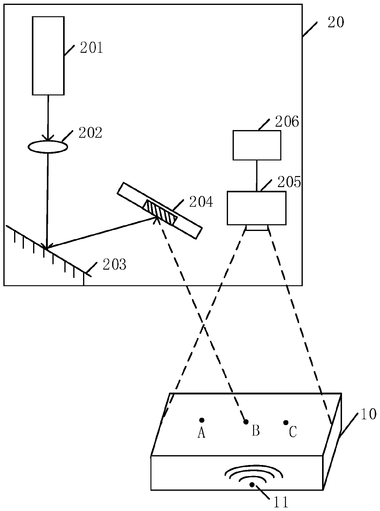
[0063] see figure 1 , figure 1 It is a schematic diagram of an application scenario of a vibration source localization device based on coherent light provided in the embodiment of the present application. Such as figure 1 As shown, the application scenario includes: a vibrating object 10 and a vibration source positioning device 20 .

[0064] Wherein, the vibrating object 10 including the vibrating source 11 can be an automatic production equipment corresponding to the field of automobile manufacturing, household appliances, transportation or food, a wearable part in a numerically controlled machine tool, or other objects such as a manipulator.

[0065] Wherein, the vibration source positioning device 20 includes: a coherent light generator 201, a lens 202, a mirror 203, a MEMS two-dimensional scanning mirror 204, a high-speed camera 205, and a processing devic...


PUM


Abstract

Disclosed in the present application are a coherent light-based vibration source positioning device and method. The method comprises: obtaining n different positions of a surface of a vibration object, the n different positions being arranged at a first interval; collecting a plurality of speckle images for each position of n different positions of the surface of the vibration object, the speckleimage being formed by reflecting coherent light onto the surface of the vibration object, and then by diffusing the reflected light; obtaining vibration oscillograms of n different positions of the surface of the vibration object according to the plurality of speckle images, and determining a vibration source position of the vibration object. By using the embodiments of the present application, anenvironment limitation of vibration source positioning can be reduced, and the efficiency and precision of vibration source positioning are improved.

Description

technical field [0001] The present application relates to the field of electronic technology, and in particular to a device and method for locating a vibration source based on coherent light. Background technique [0002] The vibration signal of the mechanical system in operation contains a wealth of information about the operating status of the mechanical system, and the vibration characteristics have a strong correspondence with the fault. The structure of the mechanical system is complex and there are many components. The collected dynamic signal is a comprehensive reflection of each component, and the influence of the propagation path increases the complexity of the signal. In addition, the early faults of many mechanical systems are weak, and the vibration sources and interference signals are mixed with each other, which makes it difficult to effectively identify and separate weak vibration signals such as early faults. Therefore, the location and identification of weak...

Claims


Application Information

Patent Timeline
Patent Type & Authority Applications(China)
IPC IPC(8): G01H9/00
CPCG01H9/00G01N21/17G01N21/27
Inventor 王星泽舒远
Owner HEREN KEJI SHENZHEN LLC
Learn More