


Quick Research
Generate reliable direction feasibility study reports for your R&D in just a few steps.

Technical Q&A
Discover and master advanced knowledge NOW. Basics, ideas, possibilities, all at once.

Find Solutions
As an expert in R&D theories, this can generate solutions to your technical problems instantly.

Evaluate Feasibility
Analyze your overall solution with one click, know your potential R&D risks in advance.

Monitor Landscape
Get weekly tech updates, stay abreast of the latest tech innovations and key insights.
A charging gun clamping seat for a charging robot
A charging gun and clamping seat technology, applied in the field of charging gun clamping seat, can solve the problems of inconvenient steering, inconvenient operation, and automatic charging is slowly put on the agenda, and achieves the effect of easy guidance and reduced friction
- Summary
- Abstract
- Description
- Claims
- Application Information
AI Technical Summary
Problems solved by technology
Method used
Image

Examples
Embodiment 1
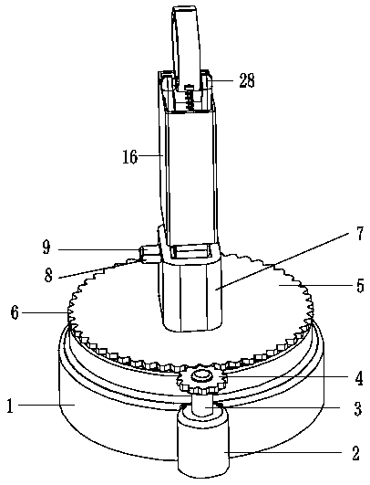
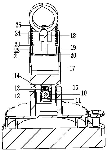
[0024] Embodiment 1: The present invention realizes the steering of the clamping device through the rotation of the steering wheel 5. By starting the lifting motor 9, the lifting motor 9 drives the inner shaft 10 to rotate, and the rotation of the inner shaft 10 drives the half gear 12 to rotate. The meshing of the gear 12 and the rack 15, the positive rotation of the motor is converted into the up and down reciprocating motion of the rectangular plate 14, and the up and down motion of the upper box 16 is adjusted through the up and down reciprocating motion of the rectangular plate 14, so that the charging robot can adapt to the charging pile and the electric motor. The height difference of the car, when it is necessary to clamp the charging gun, start the telescopic rod drive motor 18, so that the telescopic rod drive motor 18 drives the telescopic rod 19 to extend, and the extension of the telescopic rod 19 drives the long rod 20 to move downward. The downward movement of 20...
Embodiment 2
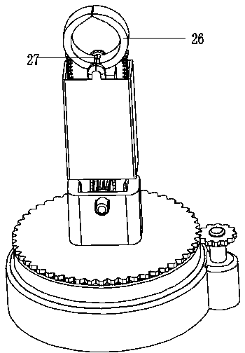
[0025] Embodiment 2: The present invention drives the motor shaft 3 to rotate by starting the motor 2, drives the drive gear 4 to rotate by the motor shaft 3, and drives the steering wheel 5 and the steering wheel 5 through the meshing of the drive gear 4 and the steering wheel 5. The clamping device at the top of the steering wheel 5 turns, and the sliding fit between the vertical shaft 32 and the ring groove 30 facilitates reducing the steering friction of the steering wheel 5, and can facilitate guidance. Through the setting of several groups of protrusions 31, the device is turned to At a certain angle, the position where the charging gun can be clamped or the working state can be stabilized during charging is not easy to be biased. This device can realize the charging robot to control the clamping force during the clamping process, without excessive clamping, and turn Precise control and the ability to adjust the clamping height.
PUM
 Abstract
Description
Claims
Application Information
 - R&D Engineer
- R&D Manager
- IP Professional
- Industry Leading Data Capabilities
- Powerful AI technology
- Patent DNA Extraction
Browse by: Latest US Patents, China's latest patents, Technical Efficacy Thesaurus, Application Domain, Technology Topic, Popular Technical Reports.
© 2024 PatSnap. All rights reserved.Legal|Privacy policy|Modern Slavery Act Transparency Statement|Sitemap|About US| Contact US: help@patsnap.com