
Low sidelobe radar antenna and vehicle-mounted radar antenna

A radar antenna and low sidelobe technology, applied in the radar field, can solve problems affecting radar performance and interference, and achieve the effects of low transmission loss, reduced coupling, and enlarged array aperture

Pending Publication Date: 2020-06-05
上海几何伙伴智能驾驶有限公司
View PDF0 Cites 3 Cited by
  • Summary
  • Abstract
  • Description
  • Claims
  • Application Information

AI Technical Summary

Problems solved by technology

[0005] In view of the shortcomings of the prior art described above, the purpose of the present invention is to provide a low-sidelobe radar antenna and a vehicle-mounted radar antenna, which are used to solve the defects of the prior art that are easy to cause interference and feeder radiation seriously affects radar performance.

Method used


Image

  • Low sidelobe radar antenna and vehicle-mounted radar antenna
  • Low sidelobe radar antenna and vehicle-mounted radar antenna
  • Low sidelobe radar antenna and vehicle-mounted radar antenna

Examples


Embodiment 1

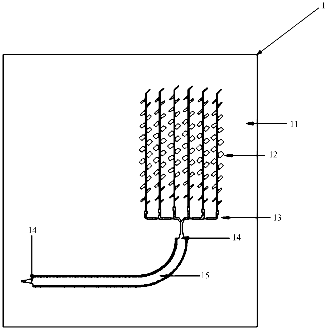
[0036] This embodiment provides a low sidelobe radar antenna, including:

[0037] Dielectric substrate;

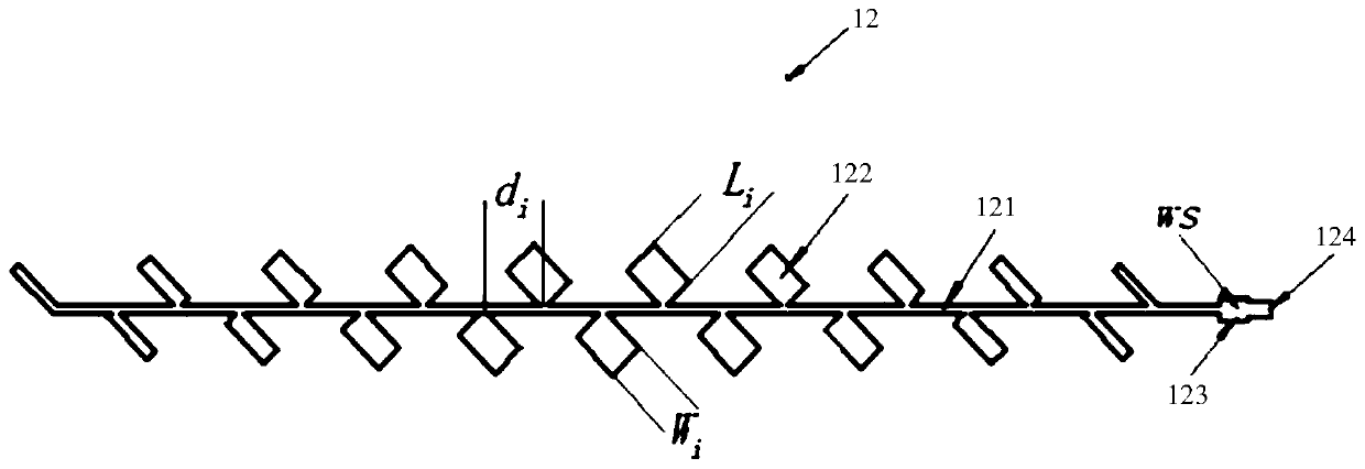
[0038] N 45° polarized linear arrays are laid on the dielectric substrate; used to form an orthogonal polarization direction with the opposing 45° polarized linear arrays; wherein, the 45° polarized linear arrays include A feeder line and several array elements arranged on the feeder line; the angle between each array element and the feeder line is 45°; N is a positive integer greater than or equal to 3.

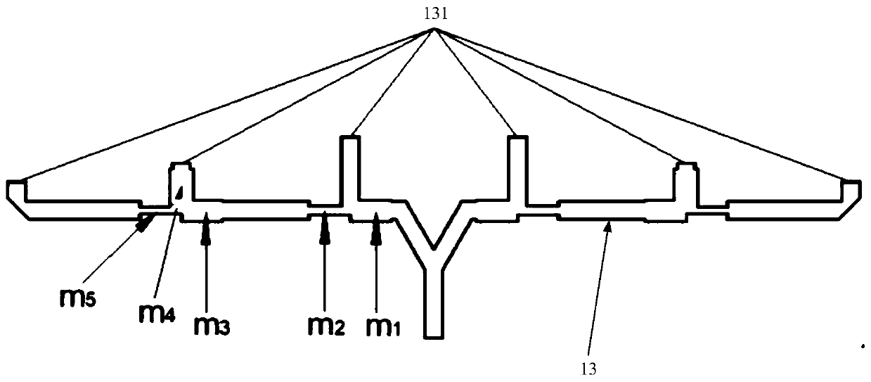
[0039] The low sidelobe radar antenna will be described in detail below with reference to figures. The low sidelobe radar antenna described in this embodiment can be applied to vehicles (for example, automobiles, tanks, armored vehicles, etc.) or blind guide equipment. see figure 1 , is a schematic plan view of the low sidelobe radar antenna in an embodiment. Such as figure 1 As shown, the low sidelobe radar antenna 1 includes a dielectric substrate 11, N 45° polari...

Embodiment 2

[0065] This embodiment provides a vehicle radar antenna, including:

[0066] Dielectric substrate;

[0067] N 45° polarized linear arrays are laid on the dielectric substrate; used to form an orthogonal polarization direction of the on-board radar antenna loaded on the opposite vehicle; wherein, the 45° polarized linear array includes A feeder line and several array elements arranged on the feeder line; the angle between each array element and the feeder line is 45°.

[0068] The on-vehicle radar antenna will be described in detail below. The vehicle-mounted radar antenna described in this embodiment is applied to a vehicle, such as a car, a tank, an armored vehicle, etc., and is used to eliminate interference to a radar antenna mounted on an oncoming vehicle. see Figure 9 , which is a schematic structural diagram of a vehicle-mounted radar antenna in an embodiment. Such as Figure 9 As shown, the vehicle radar antenna 91 in this embodiment is connected to the vehicle se...


PUM


Abstract

The invention provides a low sidelobe radar antenna and a vehicle-mounted radar antenna. The low sidelobe radar antenna comprises a dielectric substrate, andN 45-degree polarized linear arrays whichare laid on the dielectric substrate. Each 45-degree polarized linear array comprises a feeder line and a plurality of array elements arranged on the feeder line. An included angle between each arrayelement and the feeder line is 45 degrees. N is a positive integer greater than or equal to 3. According to the invention, when the low sidelobe radar antenna is opposite to the same 45-degree polarization radar, the + / -45-degree polarization orthogonality can provide enough antenna isolation, and interference of an opposite coming vehicle or an opposite radar antenna is reduced to a great extent.

Description

technical field [0001] The invention belongs to the field of radar technology, and relates to an antenna, in particular to a low sidelobe radar antenna and a vehicle-mounted radar antenna. Background technique [0002] Radar is a device used to radiate and receive electromagnetic waves and determine its detection direction. When transmitting, the radar must radiate energy to the direction that needs to be irradiated; when receiving, it only receives the echo in the detection direction as much as possible, and at the same time distinguishes the azimuth and elevation angle of the target, or one of the two. Among the three coordinates (azimuth, elevation and distance) of the target position measured by radar, the measurement of two coordinates (azimuth and elevation) is directly related to the performance of the antenna. Therefore, antenna performance is more important for radar equipment than for other electronic equipment (such as communication equipment, etc.). [0003] Th...

Claims


Application Information

Patent Timeline
Patent Type & Authority Applications(China)
IPC IPC(8): H01Q1/32H01Q1/38H01Q1/50H01Q1/52H01Q21/00H01Q21/06
CPCH01Q1/38H01Q1/50H01Q1/52H01Q1/523H01Q21/0006H01Q21/065H01Q1/3233
Inventor 李文超赵孔瑞李怡强
Owner 上海几何伙伴智能驾驶有限公司
Learn More