A kind of arc extinguishing chamber and its circuit breaker
An arc-quenching chamber and arc-quenching grid technology, applied in circuits, electrical components, electrical switches, etc., can solve the problems of increased cost, burning loss, lack of gas-producing materials and thermosetting materials, etc. The effect of performance, cost reduction and versatility
- Summary
- Abstract
- Description
- Claims
- Application Information
AI Technical Summary
Problems solved by technology
Method used
Image
Examples
Embodiment 1
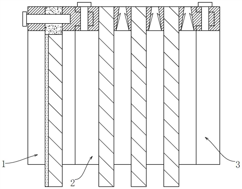
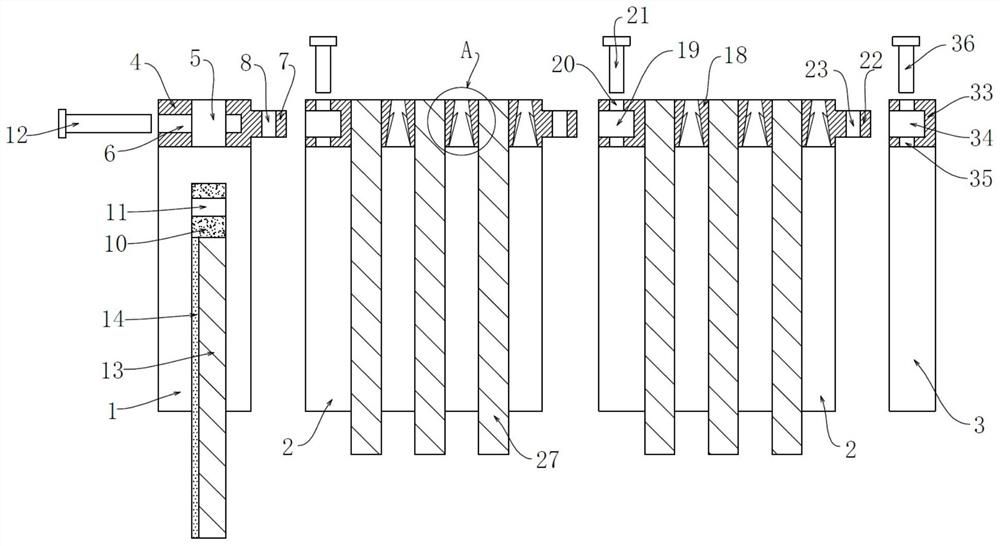
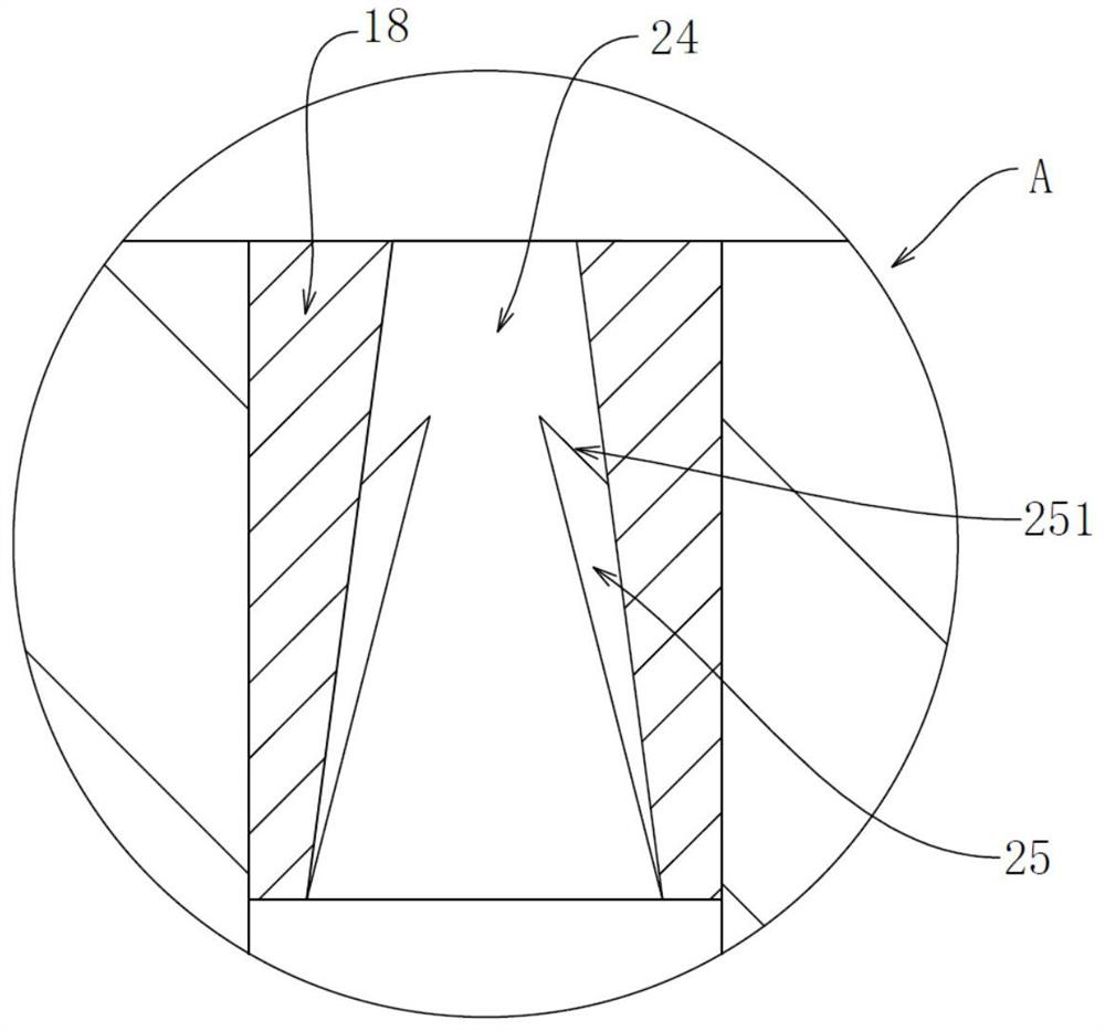
[0044] Embodiment 1: The first step is to firstly take the lower arc barrier 1 at the head end, insert the connecting part 10 of the detachable arc extinguishing grid 13 into the slot 5, and insert the fixing screws 12 at the head end through the transverse threaded holes in sequence Tighten the first 6 and the threaded connection groove 11, so that the detachable arc extinguishing grid 13 is fixed. In the second step, take a lower arc partition 2 at the middle end, and insert the first protruding rod 7 into the second installation rod 18 The first groove 19 on the top, and then tighten the connecting screw 21 through the second longitudinal threaded hole 20 and the first longitudinal threaded hole 8, and then a set of fixed arc chute on the lower arc partition wall 2 at the middle end is installed. Sheet 27, the third step is to insert the second protruding rod 22 into the second groove 34, and screw the end screw 36 through the fourth longitudinal threaded hole 35 and the thi...
Embodiment 2
[0046] Embodiment 2: The principle and use process are the same as the above-mentioned embodiment 1. The only difference is that in this embodiment, two sets of fixed arc-extinguishing grids 27 on the lower arc partition wall 2 at the middle end are used. After the above-mentioned second step is completed , insert the second protruding rod 22 into the first groove 19 on the lower arc partition wall 2 of the second group of intermediate ends, and tighten another connecting screw 21 through the second longitudinal threaded hole 20 and the third longitudinal threaded hole 23, and finally, Then insert the second protruding rod 22 at the end position into the second groove 34, and then tighten the tail screw 36 through the fourth longitudinal threaded hole 35 and the third longitudinal threaded hole 23 in sequence.
PUM
 Abstract
Description
Claims
Application Information
 - R&D
- Intellectual Property
- Life Sciences
- Materials
- Tech Scout
- Unparalleled Data Quality
- Higher Quality Content
- 60% Fewer Hallucinations
Browse by: Latest US Patents, China's latest patents, Technical Efficacy Thesaurus, Application Domain, Technology Topic, Popular Technical Reports.
© 2025 PatSnap. All rights reserved.Legal|Privacy policy|Modern Slavery Act Transparency Statement|Sitemap|About US| Contact US: help@patsnap.com


