Microscope objective lens and automatic optical inspection system

A technology of microscope objective lens and lens, applied in the optical field, can solve the problem of increasing the working distance of the objective lens, and achieve the effect of improving the operability and increasing the working distance

Active Publication Date: 2022-01-07
SHANGHAI YUWEI SEMICON TECH CO LTD
View PDF13 Cites 0 Cited by
  • Summary
  • Abstract
  • Description
  • Claims
  • Application Information

AI Technical Summary

Problems solved by technology

These difficulties restrict the increase of the working distance of the objective lens

Method used


Image

  • Microscope objective lens and automatic optical inspection system
  • Microscope objective lens and automatic optical inspection system
  • Microscope objective lens and automatic optical inspection system

Examples


Embodiment Construction

[0048] Below, the present application will be further described in conjunction with the accompanying drawings and specific implementation methods. It should be noted that, on the premise of not conflicting, the various embodiments described below or the technical features can be combined arbitrarily to form a new embodiment. .

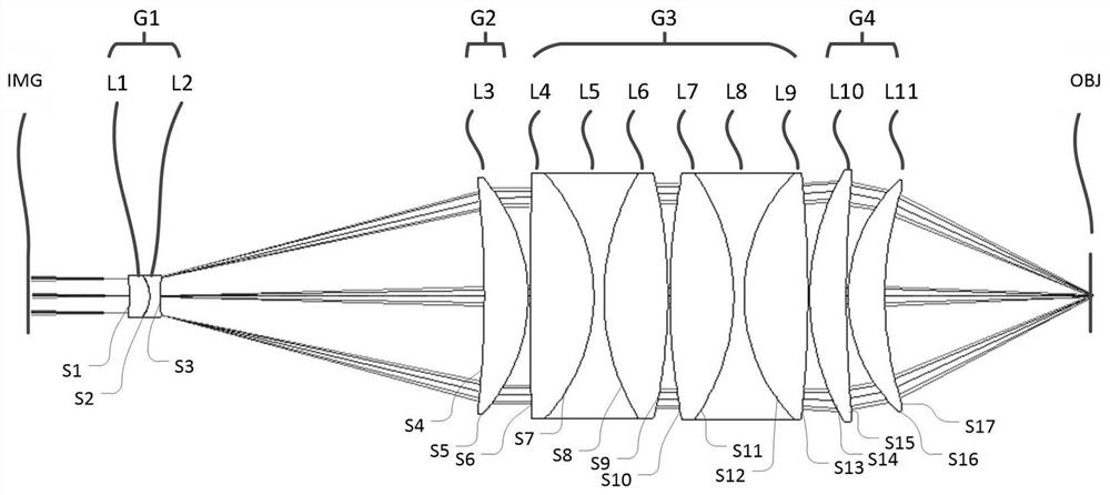
[0049] figure 1 It is a structural schematic diagram of the first embodiment of the microscope objective lens of the present invention. Such as figure 1As shown, the present embodiment provides a kind of micro objective lens, and the micro objective lens comprises at least sequentially along the optical axis from the image side (IMG) to the object side (OBJ): a first lens group G1, a second lens group G2, a third lens Group G3 and the fourth lens group G4.

[0050] The first lens group G1 has negative optical power. The first lens group G1 has a concave surface facing the image side, so that the light beam incident from the object side of the first...


PUM


Abstract

The invention provides a microscopic objective lens and an automatic optical detection system, wherein the microscopic objective lens comprises at least sequentially along the optical axis from the side of the object to the side of the image: a first lens group with negative optical power; a second lens group with positive optical focus degree, the second lens group is used to deflect the light beam incident to the second lens group from the object side of the second lens group; the third lens group has negative refractive power, and the third lens group Aberration correction for the light beam incident from the object side of the third lens group and emitted from the image side of the third lens group to the second lens group; and the fourth lens group, the first The four lens groups have positive refractive power, and the fourth lens group is used to reduce the beam incident to the fourth lens group from the object side of the fourth lens group. The invention provides a microscopic objective lens, which can obtain a high-magnification objective lens with a large working distance under the condition of keeping the numerical aperture constant and without sacrificing the aberration.

Description

technical field [0001] The invention relates to the field of optics, in particular to a microscope objective lens and an automatic optical detection system. Background technique [0002] Automatic Optical Inspection (AOI, English full name: Automatic Optical Inspection) technology can realize fast, high-precision, non-destructive inspection of wafers, chips or other objects to be tested. This technology is widely used in PCB (Printed Circuit Board, printed circuit board), IC (Integrated Circuit, integrated circuit) wafer, LED (Light-Emitting Diode, light-emitting diode), TFT (Thin Film Transistor, thin film transistor) and solar panels and many other fields. Automatic optical inspection technology generally uses broadband illumination to achieve good process adaptability, and uses long working distance objective lenses for defect detection. However, the traditional high-magnification objective lens often has a small working distance, which cannot meet the special lighting ...

Claims


Application Information

Patent Timeline
Patent Type & Authority Patents(China)
IPC IPC(8): G02B21/02G02B13/00G02B27/00G01N21/88
CPCG02B21/02G02B13/0015G02B13/006G02B27/0025G01N21/8806
Inventor 高建祥
Owner SHANGHAI YUWEI SEMICON TECH CO LTD
Why Eureka
Try Eureka