End butt joint self-anchorage type auxiliary clamping tool of stress ribs between story shear walls
A technology for clamping tools and shear walls, which is used in construction, building construction, and processing of building materials, etc., and can solve the problems affecting the efficiency of steel bar end butting, stability and reinforcement operation, construction work safety, and steel bar end butting position. Dislocation, inconvenient floor construction and lay-out operations, etc., achieve the effects of convenient alignment and reinforcement operation, tight fitting, convenient installation, disassembly and reorganization.
- Summary
- Abstract
- Description
- Claims
- Application Information
AI Technical Summary
Problems solved by technology
Method used
Image
Examples
Embodiment 1
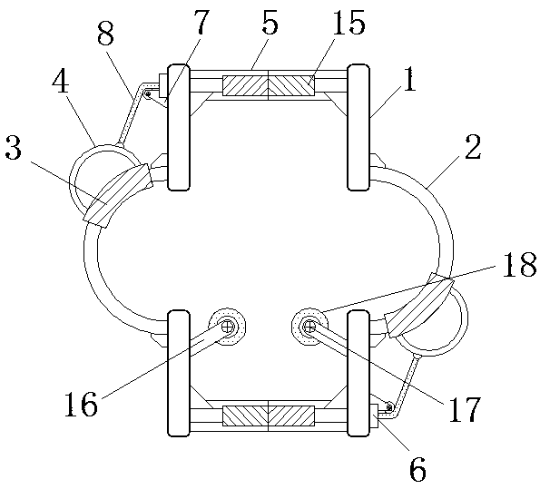
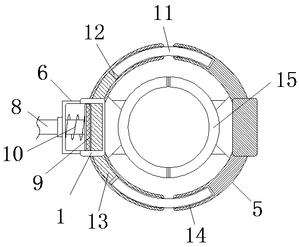
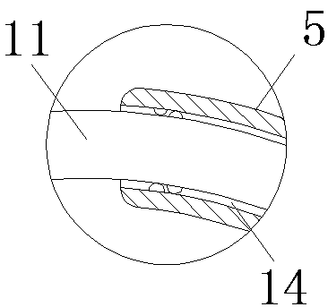
[0032] see Figure 1-5 , a self-anchored auxiliary clamping tool for docking the end of the stress tendon between the floor shear walls, including a vertical rod 1 and kerosene liquid 13, the middle part of the vertical rod 1 is fixedly installed with an arc rod 2, and the arc rod 2 The outer sleeve is provided with an installation sleeve 3, and the outer wall of the installation sleeve 3 is fixedly connected with a fixed ring 4, and a positioning ring 5 is fixedly installed between the ends of the vertical rod 1, and the outer wall of the positioning ring 5 on one side of the vertical rod 1 runs through A sealing cylinder 6 is fixed, and a guide wheel 7 is fixed on the outer wall of the positioning ring 5 below the sealing cylinder 6, and a connecting rope 8 is slidably installed on the outside of the guiding wheel 7, and the two ends of the connecting rope 8 are respectively connected to the outer wall of the fixing ring 4 and the inside of the sealing cylinder 6, and the ed...
Embodiment 2
[0037] see Figure 1-4 with Image 6 , a self-anchored auxiliary clamping tool for docking the end of the stress tendon between the floor shear walls, including a vertical rod 1 and kerosene liquid 13, the middle part of the vertical rod 1 is fixedly installed with an arc rod 2, and the arc rod 2 The outer sleeve is provided with an installation sleeve 3, and the outer wall of the installation sleeve 3 is fixedly connected with a fixed ring 4, and a positioning ring 5 is fixedly installed between the ends of the vertical rod 1, and the outer wall of the positioning ring 5 on one side of the vertical rod 1 runs through A sealing cylinder 6 is fixed, and a guide wheel 7 is fixed on the outer wall of the positioning ring 5 below the sealing cylinder 6, and a connecting rope 8 is slidably installed on the outside of the guiding wheel 7, and the two ends of the connecting rope 8 are respectively connected to the outer wall of the fixing ring 4 and the inside of the sealing cylinde...
PUM
 Abstract
Description
Claims
Application Information
 - R&D
- Intellectual Property
- Life Sciences
- Materials
- Tech Scout
- Unparalleled Data Quality
- Higher Quality Content
- 60% Fewer Hallucinations
Browse by: Latest US Patents, China's latest patents, Technical Efficacy Thesaurus, Application Domain, Technology Topic, Popular Technical Reports.
© 2025 PatSnap. All rights reserved.Legal|Privacy policy|Modern Slavery Act Transparency Statement|Sitemap|About US| Contact US: help@patsnap.com


