A construction method for steel box girder unloading

A construction method and technology of steel box girders, applied in bridges, bridge construction, erection/assembly of bridges, etc., can solve problems that cannot be realized, and achieve the effects of safety assurance, easy operation, and reduction of time for high-altitude operations

Active Publication Date: 2021-11-19
SINOHYDRO BUREAU 11 CO LTD
View PDF21 Cites 0 Cited by
  • Summary
  • Abstract
  • Description
  • Claims
  • Application Information

AI Technical Summary

Problems solved by technology

That is to say, the current unloading method relies on the high-altitude in-situ assembly method supported by the tire frame to construct and unload the steel box girder. When there is no support or tire frame for arranging the jack, the above method will not be realized

Method used


Image

  • A construction method for steel box girder unloading
  • A construction method for steel box girder unloading

Examples


Embodiment Construction

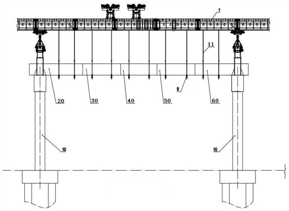
[0055] like figure 1 , figure 2 FIG, uninstall the steel box girder construction method, comprising the steps of:

[0056] Step 1, 3 on the pre-unloading means erecting machine section 1, section 1 moves to the erecting machine 10 pier;

[0057] Step 2, the segment erecting machine 1 is mounted on the unloading apparatus 3;

[0058] Step 3, lifting steel box girder section 12;

[0059] Step 4, docking boom 4 and the lower boom 6, the suspension steel box girder section 12;

[0060] Step 5, assembled and welded to steel box girder section 12, is formed across the entire steel box girder and unloading;

[0061] Step 6, 9 separate steel box girder and the bottom surface of a span of the balance beam.

[0062] Further, step 1, comprising the steps of:

[0063] Step 1.1, unloading device 3 is assembled, an upper sleeve unloading device 3 (not shown), a lower casing (not shown), locking means (not shown), cock type valve (not shown in FIG. ), and the upper casing sleeve is provided in t...


PUM


Abstract

The invention belongs to the technical field of steel bridge construction, and in particular relates to a steel box girder unloading construction method, comprising the following steps: Step 1, the preloading and unloading device is placed on the segmental assembly bridge erecting machine, and the segmental assembly bridge erection machine moves to Bridge pile; step 2, install unloading device on the segmental assembly bridge erecting machine; step 3, hoist the segmental steel box girder; step 4, connect the upper boom and lower boom, hang the segmental steel box girder; step 5, assemble and weld Fix the segmental steel box girder to form a full-span steel box girder and unload it; step 6, the bottom surface of the full-span steel box girder is separated from the balance beam. The beneficial effects provided by the invention are that the sinking speed can be effectively controlled, the unloading process can be made stable, balanced, synchronized and orderly, and the construction quality and personnel safety can be reliably guaranteed.

Description

Technical field [0001] The present invention belongs to the technical field steel bridge construction, particularly, it relates to a method for the steel box girder construction unloading. Background technique [0002] Unloading steel box girder is a key step in the construction, which aims: removal during construction or stent tire rack for supporting the steel box girder, the assembly, the force during the welding bead stent or frame, is converted into the final steel Box itself load-bearing structure of the steel box girder member completely out of the bracket, with the design and keep the linear dimension after elevation steel box girder and bridge into uniform in shape. Unloading step after completion of welding steel box girder assembly, during unloading, the respective support points required, in accordance with a reasonable order, step by step, subregional coordinated reduced simultaneously removing the stand until the supporting force to ensure that the force balance and...

Claims


Application Information

Patent Timeline
Patent Type & Authority Patents(China)
IPC IPC(8): E01D21/00E01D2/04
CPCE01D2/04E01D21/00
Inventor 卢俊生孙建国李有道王显鹤闫现啟
Owner SINOHYDRO BUREAU 11 CO LTD
Why Eureka
Try Eureka