Webbing winding device
A technology of winding device and seat belt, applied in the direction of seat belt, transportation and packaging, vehicle parts, etc., can solve the problem of noise and so on
- Summary
- Abstract
- Description
- Claims
- Application Information
AI Technical Summary
Problems solved by technology
Method used
Image

Examples
no. 1 approach
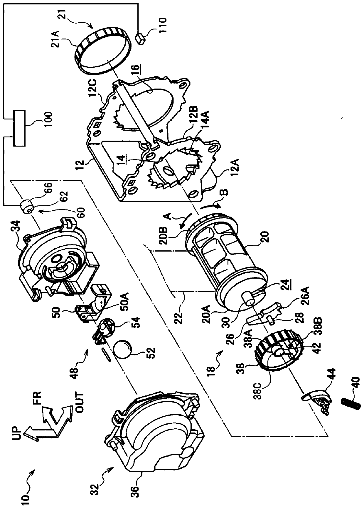
[0032] exist figure 1 In FIG. 2 , the seat belt take-up device 10 according to the first embodiment of the present invention is shown in an exploded perspective view viewed from the rear side, the outer side, and the oblique direction from the upper side. In addition, in the figure, arrow FR indicates the vehicle front side in the state where the seat belt retractor 10 is mounted on the vehicle, arrow OUT indicates the vehicle width direction outer side, and arrow UP indicates the vehicle upper side. In addition, in the following description, the case where the front-rear direction and the up-down direction are simply shown means the front-rear direction in the vehicle front-rear direction and the up-down direction in the vehicle up-down direction.
[0033] Such as figure 1 As shown, the seat belt take-up device 10 of the present embodiment includes a frame 12 formed in a substantially U-shape as viewed from the vehicle upper side. The frame 12 includes: a back panel 12A e...
no. 2 approach
[0082] In the first embodiment, the control device 100 calculates the acceleration of the seat belt 22 based on the angular velocity calculated from the rotation angle and a predetermined coefficient. Here, although the prescribed coefficient refers to the reference winding diameter of the seat belt 22 in the spool 20, the winding diameter of the seat belt 22 increases as the winding amount of the seat belt 22 in the spool 20 increases. The amount of winding of the seat belt 22 is decreased to decrease. Therefore, in the second embodiment, the acceleration of the seat belt 22 is corrected based on a certain rotation angle related to the winding amount of the seat belt 22 .
[0083] For example, the control device 100 can correct the acceleration of the seat belt 22 based on a calculation formula that takes the thickness of the seat belt 22 into account in the total rotation angle of the belt shaft 20 . Also, for example, the control device 100 includes a correction table that...
no. 3 approach
[0089] The seat belt take-up device 10 of the third embodiment uses a pull-out sensor for detecting the pull-out amount of the seat belt 22 for the control of the lock mechanism 18 . In the present embodiment, a pull-out sensor (not shown) is provided on the path of the seat belt 22 such as on the upper portion of the frame 12 . As the withdrawal amount sensor, for example, a laser type displacement gauge can be applied. In addition, the pull-out sensor of this embodiment is electrically connected to the control device 100, and calculates and acquires the acceleration of the seat belt 22 based on the pull-out amount of the seat belt 22 acquired by the pull-out sensor. In addition, in this embodiment, the sensor input to the control device 100 is replaced by the pull-out sensor from the rotation angle sensor 110 of the first embodiment, and the rest of the structure and the control method based on the calculated acceleration and jerk are the same as those of the first embodimen...
PUM
 Abstract
Description
Claims
Application Information
 - Generate Ideas
- Intellectual Property
- Life Sciences
- Materials
- Tech Scout
- Unparalleled Data Quality
- Higher Quality Content
- 60% Fewer Hallucinations
Browse by: Latest US Patents, China's latest patents, Technical Efficacy Thesaurus, Application Domain, Technology Topic, Popular Technical Reports.
© 2025 PatSnap. All rights reserved.Legal|Privacy policy|Modern Slavery Act Transparency Statement|Sitemap|About US| Contact US: help@patsnap.com