Method for correcting perpendicularity between Y axis sliding saddle and X axis workbench of large numerical control gantry machining center

A machining center and calibration method technology, which is applied in metal processing equipment, metal processing machine parts, manufacturing tools, etc., can solve the problems of low calibration accuracy of XY axis verticality, achieve convenient secondary calibration, reduce influence, and improve precision Effect

Inactive Publication Date: 2020-06-05
广州义同机械实业有限公司
View PDF6 Cites 2 Cited by
  • Summary
  • Abstract
  • Description
  • Claims
  • Application Information

AI Technical Summary

Problems solved by technology

[0004] The purpose of the present invention is to provide a method for correcting the perpendicularity between the Y-axis saddle and the X-axis worktable of a large-scale CNC gantry machining center, aiming at solving the problem of low precision in the correction of the XY-axis perpendicularity by using a square marble square ruler in the existing technology question

Method used


Image

  • Method for correcting perpendicularity between Y axis sliding saddle and X axis workbench of large numerical control gantry machining center
  • Method for correcting perpendicularity between Y axis sliding saddle and X axis workbench of large numerical control gantry machining center
  • Method for correcting perpendicularity between Y axis sliding saddle and X axis workbench of large numerical control gantry machining center

Examples


Embodiment Construction

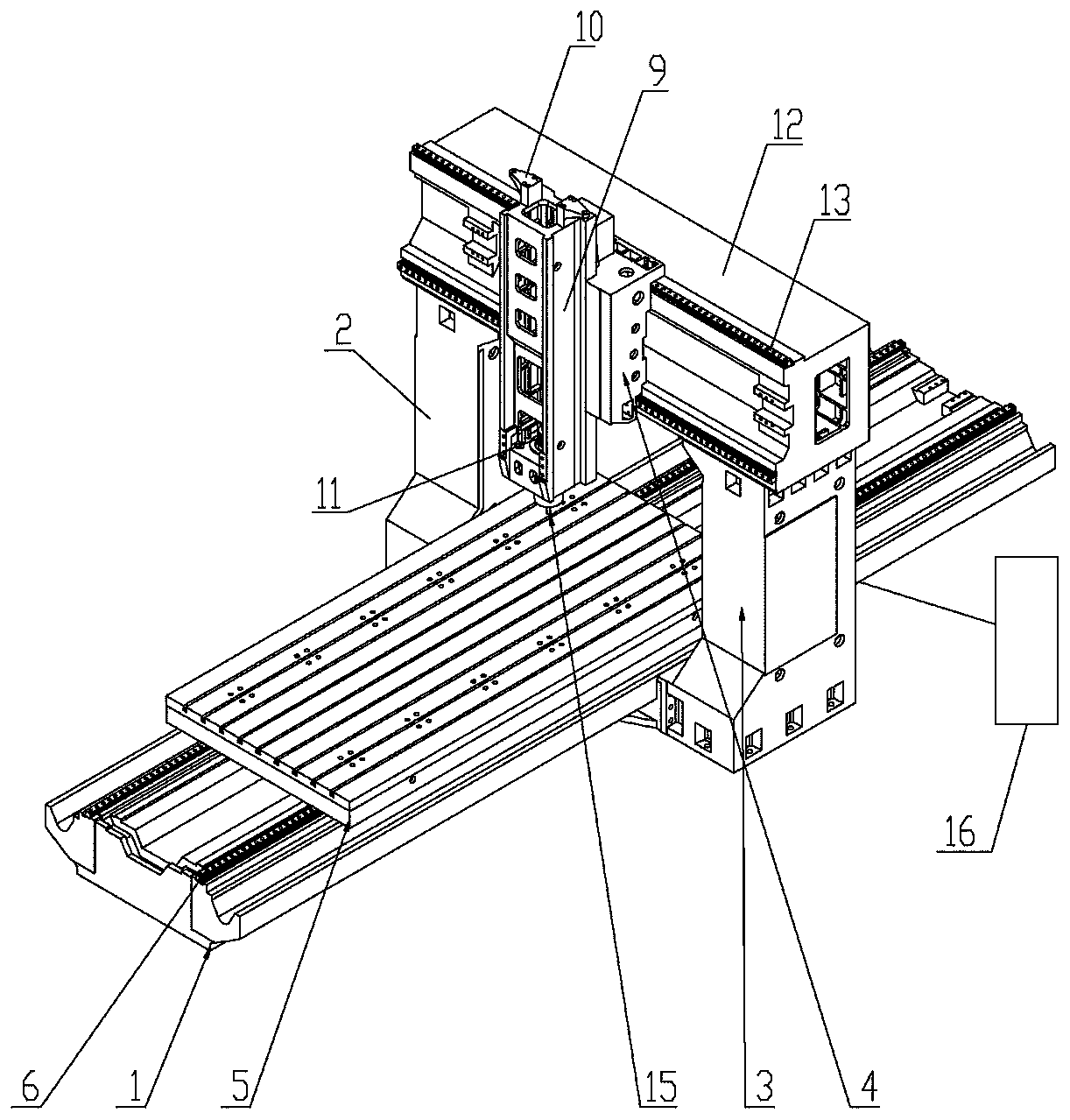
[0031] Step 1: The gantry base (1) is installed on the foundation, adjust the levelness of the gantry base (1), the left column (2) and the right column (3) are respectively installed in the middle of both sides of the gantry base (1), and the Y-axis beam (12) A machine tool that is installed above the left column (2) and the right column (3) at the same time to form an integral structure;

[0032] Step 2: The X-axis guide rail (6) is installed on the surface of the gantry base (1), and the X-axis workbench (5) is installed above the X-axis guide rail (6). ) to move left and right, adjust the parallelism of the X-axis guide rail (6), and correct the straightness of the X-axis travel to ensure that it is less than 0.04mm. The Y-axis beam (12) is equipped with a Y-axis guide rail (13) on the side surface. 13) The Y-axis saddle (4) is installed on it, and the Y-axis saddle (4) can move back and forth on the Y-axis guide rail (13), adjust the parallelism of the Y-axis guide rail (...


PUM


Abstract

The invention provides a method for correcting perpendicularity between a Y axis sliding saddle and an X axis workbench of a large numerical control gantry machining center. The method for correctingperpendicularity between the Y axis sliding saddle and the X axis workbench of the large numerical control gantry machining center comprises a gantry base, a left stand column, a right stand column, amachined workpiece, a right-angle workpiece, a cross beam fine adjustment device, an articulated arm measuring instrument, a motor and related power distribution; the fine correcting process comprises the steps that a numerical control gantry machine tool is used for fine correcting of the full-stroke right-angle workpiece, the articulated arm measuring instrument is used for measuring an included angle of the machined workpiece in the XY plane; and according to the measurement result, the machining size of the square workpiece is modified, the measurement result is added between XY of the square workpiece and correcting is carried out, trial machining is carried out again according to a regenerated model, a cross beam is adjusted to enable the Y axis to be parallel to the Y direction ofthe workpiece, it is guaranteed that the precision is within the range of 0.015 mm (within any 1000 mm stroke), after the adjustment is completed, machining is carried out by using a normal program, after machining is completed, a joint arm is used for measuring the included angle of the XY plane, and the process continues to be repeated if requirements are not met. According to the method for correcting perpendicularity between the Y axis sliding saddle and the X axis workbench of the large numerical control gantry machining center, the precision is high, and the XY perpendicularity precisionof a gantry can be corrected to 0.02 to 0.03 mm.

Description

technical field [0001] The invention belongs to the technical field of related large-scale numerical control gantry processing, and in particular relates to a method for correcting the perpendicularity between a Y-axis saddle and an X-axis workbench of a large-scale numerically controlled gantry processing center. Background technique [0002] With the development of the manufacturing industry, large-scale CNC gantry machining centers have been used more and more. In the automotive industry, the processing accuracy required for the bottom plate of fixtures and inspection tools is getting higher and higher, and the dimensional accuracy between holes is very high, and the requirement must reach ±0.15. The error of the verticality of the XY axis of the large-scale CNC gantry machining center has a great influence on the positional and dimensional accuracy of the hole and the hole diameter. [0003] Using modern measurement technology, the XY axis angle of the right-angle workp...

Claims


Application Information

Patent Timeline
Patent Type & Authority Applications(China)
IPC IPC(8): B23Q17/00
CPCB23Q17/00
Inventor 卢跃刘付伟夫胡培才王青君刘之亨李明冯保荣
Owner 广州义同机械实业有限公司
Why Eureka
Try Eureka