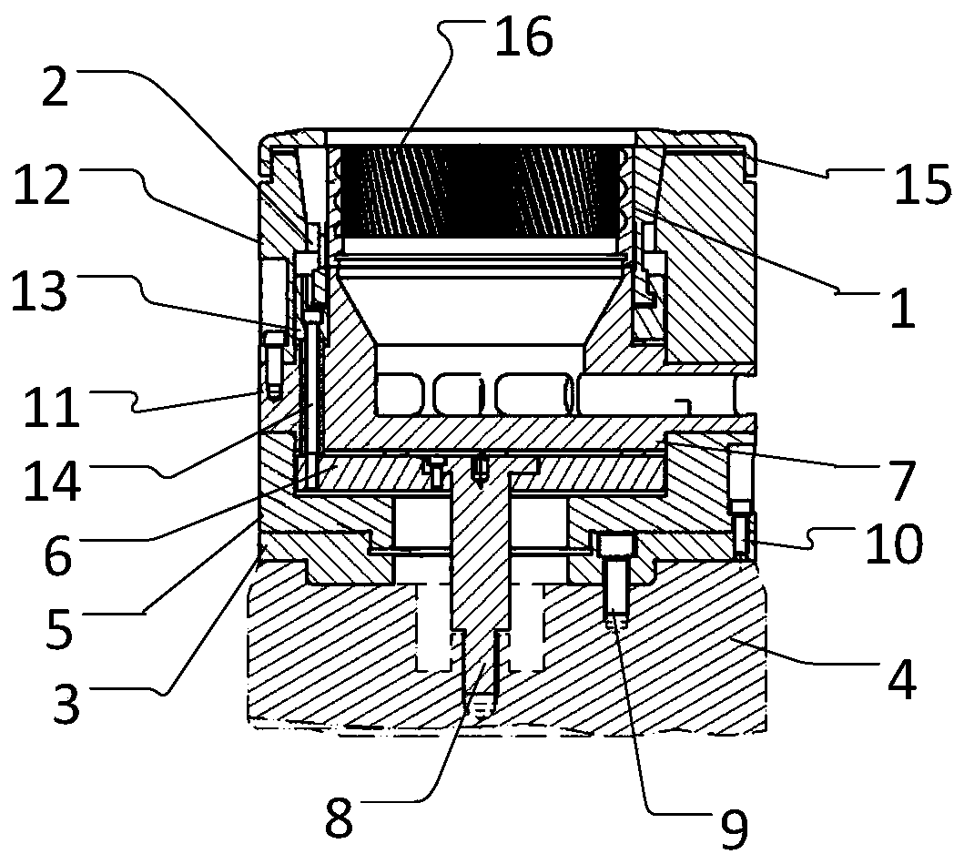
Skiving machine expansion sleeve type clamp

A technology of expansion sleeve and gear cutting machine, which is applied in the direction of gear cutting machine, gear teeth, mechanical equipment, etc. It can solve the problems of affecting the processing accuracy of the ring gear and the processing accuracy is not high, so as to improve the gear cutting accuracy, improve the processing accuracy, prevent The effect of workpiece deformation

Active Publication Date: 2020-06-05
CHONGQING MACHINE TOOL GROUP
View PDF7 Cites 0 Cited by
  • Summary
  • Abstract
  • Description
  • Claims
  • Application Information

AI Technical Summary

Problems solved by technology

However, it is found from the process of use that the hydraulic environment changes greatly when the hydraulic chuck is fixed, and the machining accuracy is not high. On the other hand, the insecure fixation between the fixture itself and the working table of the gear turning machine will affect the machining accuracy of the ring gear

Method used


Image

  • Skiving machine expansion sleeve type clamp

Examples


Embodiment Construction

[0017] Embodiments of the present invention are described below through specific examples, and those skilled in the art can easily understand other advantages and effects of the present invention from the content disclosed in this specification. The present invention can also be implemented or applied through other different specific implementation modes, and various modifications or changes can be made to the details in this specification based on different viewpoints and applications without departing from the spirit of the present invention. It should be noted that the diagrams provided in the following embodiments are only schematically illustrating the basic concept of the present invention, and the following embodiments and the features in the embodiments can be combined with each other in the case of no conflict.

[0018] Wherein, the accompanying drawings are for illustrative purposes only, and represent only schematic diagrams, rather than physical drawings, and should...


PUM


Abstract

The invention belongs to the technical field of machine tool clamps, and relates to a skiving machine expansion sleeve type clamp. The clamp comprises a clamp sleeve used for clamping a workpiece, wherein elastic chucks are arranged on the periphery of the clamp sleeve and apply clamping force pointing to the geometric center of the clamp sleeve to the clamp sleeve, a clamp body is arranged at oneend of the clamp sleeve and provides structural support for the clamp sleeve and the elastic chucks, the elastic chucks are symmetrically arranged on the periphery of the clamp sleeve along the geometric center line of the clamp sleeve, and the elastic chucks are of a cylindrical structure. According to the clamp, workpiece positioning precision is improved, workpiece deformation is prevented, then gear cutting precision is improved, the gear cutting service life of a cutter can be prolonged to a certain extent, the structure is simple, the rotational inertia of a skiving machine workbench isreduced, and it is guaranteed that a machine tool can be safely and stably stopped.

Description

technical field [0001] The invention belongs to the technical field of machine tool clamps, and relates to an expansion sleeve type clamp for gear turning machines. Background technique [0002] In the field of mechanical processing, it is usually necessary to locate and fix the workpiece to be processed, and the most common method for radial positioning and fixing of the workpiece is to use a fixture. At present, hydraulic chucks are often used to fix the ring gear when machining the gear ring. However, it is found from the process of use that the hydraulic environment changes greatly when the hydraulic chuck is fixed, and the machining accuracy is not high. Contents of the invention [0003] In view of this, the purpose of the present invention is to provide a jig with stable function, precise positioning, and firm fixation, which is used for tooth cutting of an internal ring gear. [0004] To achieve the above object, the present invention provides the following techn...

Claims


Application Information

Patent Timeline
Patent Type & Authority Applications(China)
IPC IPC(8): B23F23/06
CPCB23F23/06
Inventor 曾令万杨灿辉彭福羽孙蔚何顺围
Owner CHONGQING MACHINE TOOL GROUP
Why Eureka
Try Eureka