
Throttle device

A technology of throttling devices and throttle valves, which is applied to fuel injection devices, charging systems, machines/engines, etc., and can solve the problems of idling adjustment valve man-hours or increased manufacturing costs

Active Publication Date: 2020-06-02
MIKUNI CORP
View PDF21 Cites 1 Cited by
  • Summary
  • Abstract
  • Description
  • Claims
  • Application Information

AI Technical Summary

Problems solved by technology

[0006] Therefore, there is a concern that readjustment of the idling adjustment valve or cleaning by removal, etc. are required
[0007] In addition, since various passages are formed in the idling control valve, man-hours and manufacturing costs for quality control of the idling control valve increase.

Method used


Image

  • Throttle device
  • Throttle device
  • Throttle device

Examples


Embodiment Construction

[0039] As follows, while referring to Figure 1 to Figure 11 , while describing the embodiments of the present invention.

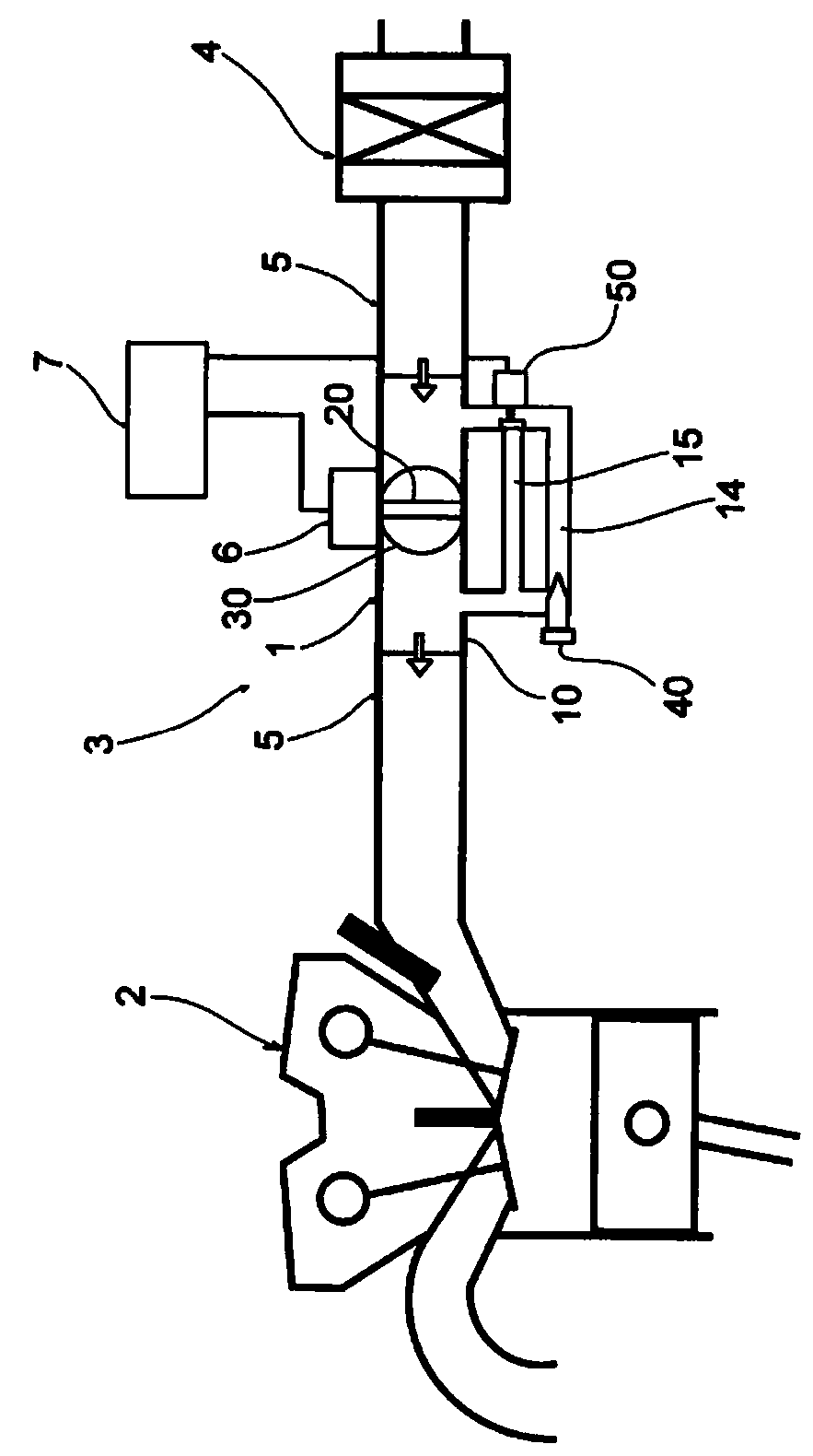
[0040] Such as figure 1 As shown, the throttle device 1 of the present embodiment is installed in the middle of the intake pipe 5 on the downstream side of the air cleaner 4 in the intake system 3 of the engine 2 mounted on a motorcycle or the like.

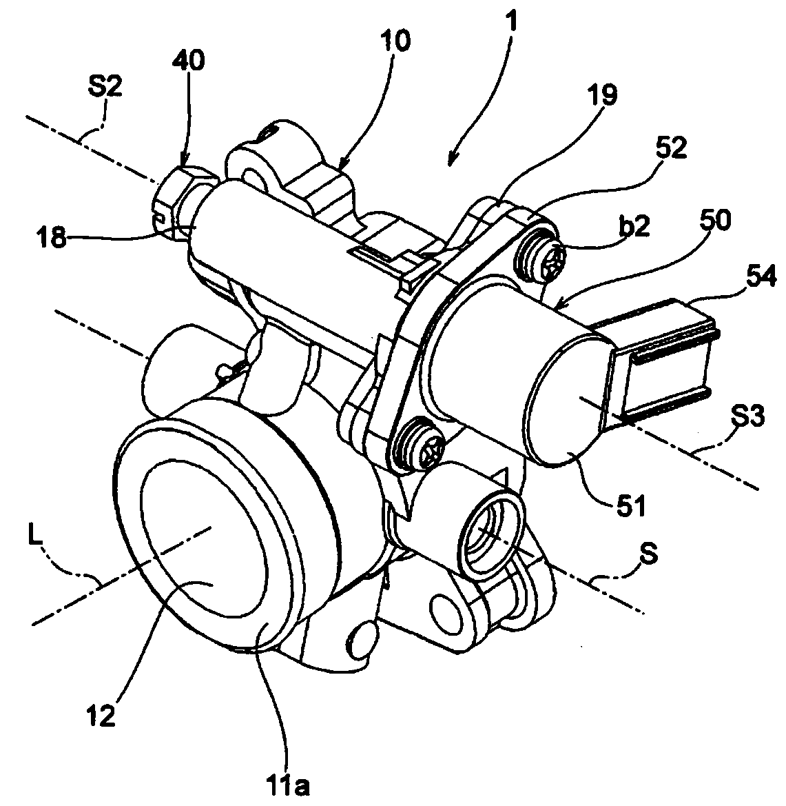
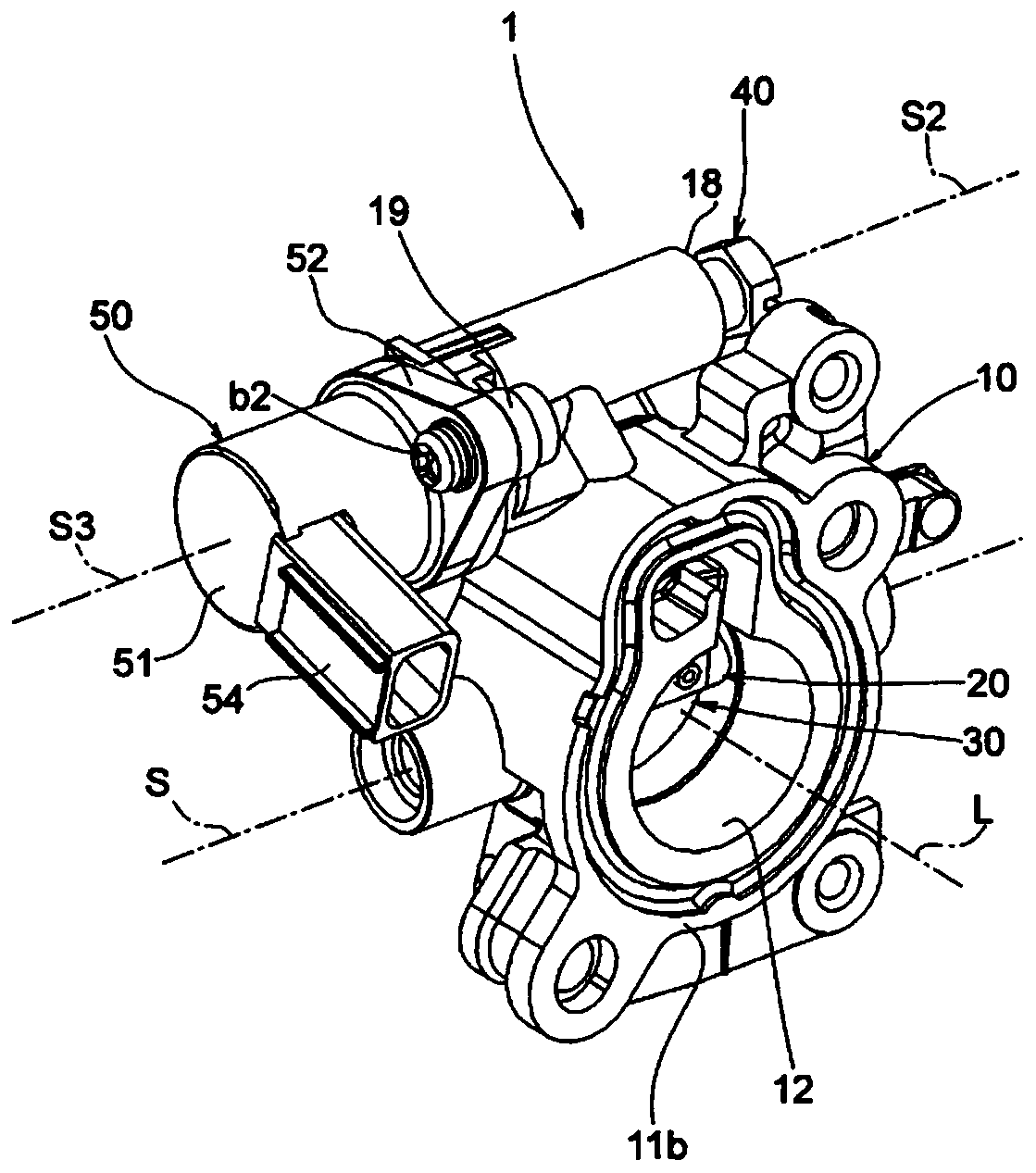
[0041] The throttling device 1 includes: a body 10 , a valve shaft 20 , a throttle valve 30 , an adjusting screw 40 screwed with the body 10 , and a solenoid valve 50 installed on the body 10 .

[0042] Here, the valve shaft 20 is rotationally driven appropriately in response to a control signal from the control unit 7 by the drive source 6 provided adjacent to the throttle device 1 .

[0043] In addition, duty control of the solenoid valve 50 is appropriately performed in response to a control signal from the control unit 7 .

[0044] The body 10 is formed of metal materials such as aluminum, and include...


PUM


Abstract

A throttle device of the present invention is provided with: a throttle valve (30) which opens and closes a main passageway (12); a body (10) which includes the main passageway (12) and a sub-passageway (14) that bypasses the throttle valve (30); and an adjusting screw (40) which is threaded into the body (10) to adjust the passageway area of the sub-passageway (14). The body (10) includes a collision wall (16) which is formed upstream of the adjusting screw (40) so as to protrude into the sub-passageway (14), and with which a fluid is caused to collide. In this way, it is possible to capture,upstream of the adjusting screw, foreign matter that has entered intake air, and to maintain the initial setting of the adjusting screw for a long period.

Description

technical field [0001] The present invention relates to a throttle device disposed in an intake system of an engine mounted on a motorcycle, and more particularly to a throttle device including an adjusting screw for idling adjustment in a sub passage bypassing a throttle valve. Background technique [0002] As a conventional throttling device, there is known an engine idling adjustment device that includes a main body that defines an intake passage, a throttle valve that opens and closes the intake passage, and a throttle valve formed on the main body so as to bypass the throttle valve. The bypass channel of the bypass channel, the idling adjustment valve screwed into the nearest downstream of the metering hole of the bypass channel to adjust the flow rate, the idling adjustment valve has a screw shaft screwed into the screw hole of the body, a metering groove formed on the outer periphery, and a metering groove formed on the The internal termination hole, a plurality of th...

Claims


Application Information

Patent Timeline
Patent Type & Authority Applications(China)
IPC IPC(8): F02D9/02F02M69/32
CPCF02D9/02F02M69/32
Inventor 関口眞一川口裕美北冈竜也
Owner MIKUNI CORP
Learn More