
Static electricity removing device of gluing machine

A technology of static electricity removal device and gluing machine, which is applied in the direction of static electricity and electrical components, and can solve the problems of conductive wires easily polluting the production workshop, conductive wires falling out, and affecting the quality of electronic protective films.

Inactive Publication Date: 2020-06-02
惠州市博泰涂布科技有限公司
View PDF0 Cites 0 Cited by
  • Summary
  • Abstract
  • Description
  • Claims
  • Application Information

AI Technical Summary

Problems solved by technology

[0003] However, the static removal brush is directly fixed at the winding and unwinding places. The traditional static removal brush is generally composed of an aluminum frame, an upper splint, a lower splint and a conductive wire. The upper and lower splints are respectively arranged on the aluminum frame. The wire is embedded between the upper and lower splints, but the conductive wire is very easy to fall out of the upper and lower splints during the use or handling of the antistatic brush of this structure, and the dropped conductive wire is easy to contaminate In the production workshop, at the same time, such a static removal brush has a short service life. After the conductive wire falls, the effect of removing static electricity on the original film is poor, which in turn makes the follow-up oily glue less adherent to the original film, affecting production. The quality of the electronic protective film

Method used


Image

  • Static electricity removing device of gluing machine

Examples


Embodiment Construction

[0021] In order to facilitate the understanding of the present invention, the present invention will be described more fully below with reference to the associated drawings. Preferred embodiments of the invention are shown in the accompanying drawings. However, the present invention can be embodied in many different forms and is not limited to the embodiments described herein. On the contrary, the purpose of providing these embodiments is to make the disclosure of the present invention more thorough and comprehensive.

[0022] It should be noted that when an element is referred to as being “fixed” to another element, it can be directly on the other element or there can also be an intervening element. When an element is referred to as being "connected to" another element, it can be directly connected to the other element or intervening elements may also be present. The terms "vertical," "horizontal," "left," "right," and similar expressions are used herein for purposes of ill...


PUM

PropertyMeasurementUnit
Lengthaaaaaaaaaa

Abstract

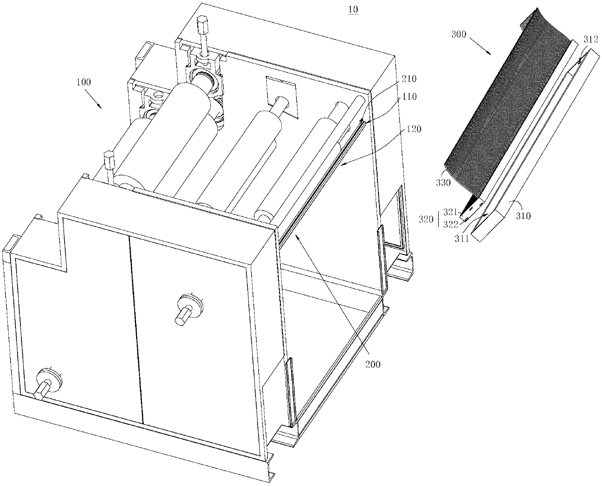
The invention discloses a static electricity removing device of a gluing machine. The device comprises a gluing machine, a mounting rod and a static electricity removing assembly, and the mounting rodis accommodated in an electrostatic elimination area; the static electricity removing assembly comprises a fixing frame, a planting plate and a plurality of conductive wires; the planting plate comprises a plate body, a first clamping and embedding piece and a second clamping and embedding piece; a plurality of planting grooves are formed in one side surface, far away from the fixing frame, of the plate body; each conductive wire is correspondingly clamped in one planting groove; the mounting rod is used for mounting and fixing the electrostatic eliminating assembly to prevent the static electricity removing assembly from falling off, a plurality of planting grooves are formed in one side surface, far away from the fixing frame, of the plate body, each conductive wire is correspondingly clamped in one planting groove, each conductive wire is arranged towards the roller group of the gluing machine; the planting grooves are used for fixing and clamping the conductive wires, each conductive wire is firmly clamped in the corresponding planting groove, falling of the conductive wires can be reduced, the number of the falling conductive wires is reduced, and therefore the static electricity removing effect of the static electricity removing assembly can be effectively guaranteed, and the gluing quality of the electronic protection film can be effectively improved through the staticelectricity removing device of the gluing machine.

Description

technical field [0001] The invention relates to the technical field of oily film production, in particular to a static electricity removal device for a gluing machine. Background technique [0002] Usually, when producing electronic protective films, it is necessary to carry out gluing treatment on the original film material. Before gluing, the original film needs to be subjected to a series of treatments, including stretching, corona treatment, and static electricity removal. Make the surface of the original film have higher adhesion. [0003] However, the static removal brush is directly fixed at the rewinding and unwinding place. The traditional static removal brush is generally composed of an aluminum frame, an upper splint, a lower splint and a conductive wire. The upper and lower splints are respectively arranged on the aluminum frame. The wire is embedded between the upper and lower splints, but the conductive wire of this structure is easy to fall out from the upper...

Claims


Application Information

Patent Timeline
IPC IPC(8): H05F3/00
CPCH05F3/00
Inventor 黄东清
Owner 惠州市博泰涂布科技有限公司
Learn More