
Chip pin coplanarity detection device

A detection device and coplanarity technology, which is applied in the direction of measuring devices, optical devices, instruments, etc., can solve the problems of affecting imaging, easy tilting of tray placement, lack of positioning mechanism for chip trays, etc., to avoid detection deviation, High degree of automation, avoid damage to the chip effect

Pending Publication Date: 2020-06-02
TIANJIN TIANMEN JINBAO TECH CO LTD
View PDF0 Cites 1 Cited by
  • Summary
  • Abstract
  • Description
  • Claims
  • Application Information

AI Technical Summary

Problems solved by technology

[0003] In the prior art, there are related equipment for chip pin coplanarity detection, but most of the chips are picked and placed manually, which can easily cause damage to the chip, and the tray where the chip is placed lacks a positioning mechanism, and the placement of the tray is easy to tilt, which affects imaging , which ultimately affects the detection results of pin coplanarity

Method used


Image

  • Chip pin coplanarity detection device
  • Chip pin coplanarity detection device
  • Chip pin coplanarity detection device

Examples


Embodiment Construction

[0026] It should be noted that, in the case of no conflict, the embodiments of the present invention and the features in the embodiments can be combined with each other.

[0027] In describing the present invention, it should be understood that the terms "center", "longitudinal", "transverse", "upper", "lower", "front", "rear", "left", "right", " The orientations or positional relationships indicated by "vertical", "horizontal", "top", "bottom", "inner" and "outer" are based on the orientations or positional relationships shown in the drawings, and are only for the convenience of describing the present invention and Simplified descriptions, rather than indicating or implying that the device or element referred to must have a particular orientation, be constructed and operate in a particular orientation, and thus should not be construed as limiting the invention. In addition, the terms "first", "second", etc. are used for descriptive purposes only, and should not be understood ...


PUM


Abstract

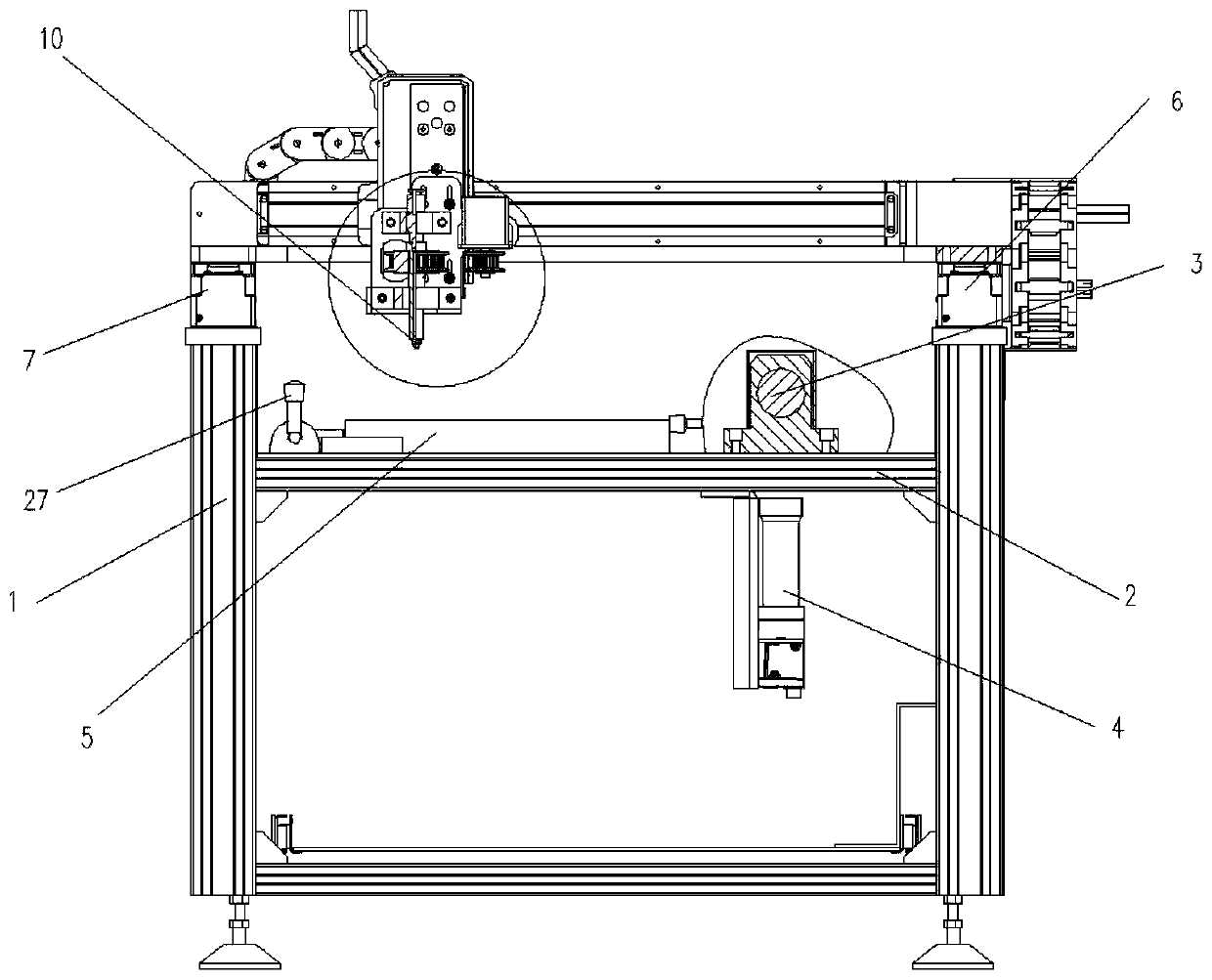
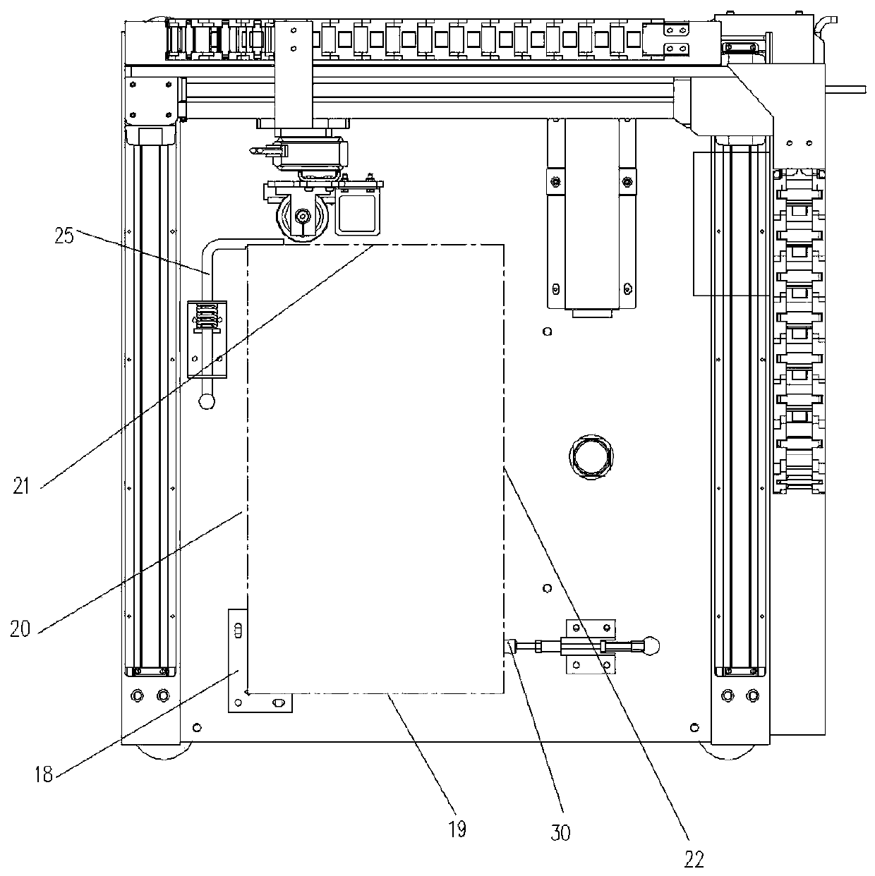
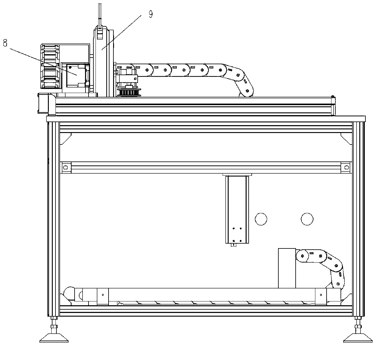
The invention provides a chip pin coplanarity detection device which comprises a rack, a workbench, a detection mechanism, a tray, a tray positioning mechanism and a chip carrying mechanism, and is characterized in that the tray is used for placing a chip and is arranged on the workbench; the tray positioning mechanism is arranged at the periphery of the tray and is used for positioning the side surface of the tray; the chip carrying mechanism is arranged above the tray and comprises an XYZ moving assembly and a taking and placing assembly, the taking and placing assembly is connected with theXYZ moving assembly, and the XYZ moving assembly is used for driving the taking and placing assembly to place the chip in the tray. By arranging the tray positioning mechanism, the positioning of thetray on the workbench can be achieved, and the detection deviation caused by the deflection of the tray can be avoided. By arranging the chip carrying mechanism, the chip can be automatically carriedto the tray, so that the automation degree is high, and the chip is prevented from being damaged in the carrying process.

Description

technical field [0001] The invention belongs to the technical field of integrated circuit detection equipment, and in particular relates to a chip pin coplanarity detection device. Background technique [0002] The coplanarity of the chip pins refers to the vertical height deviation of the surface mount component pins, that is, the vertical distance between the horizontal plane formed by the highest pin sole and the horizontal plane formed by the lowest pin sole. In the surface mount production process of circuit boards, in order to ensure the quality of mounting, the mounting process puts forward quite high requirements on the coplanarity of the pins. When the coplanarity of the pins exceeds a certain range, some leads of the device The surface of the heel printed circuit board pad cannot be in close contact, which may lead to defects such as virtual soldering, missing soldering, and virtual connection. Therefore, the coplanarity of chip pins is an important factor affectin...

Claims


Application Information

Patent Timeline
Patent Type & Authority Applications(China)
IPC IPC(8): G01B11/00G01B11/06
CPCG01B11/00G01B11/0608
Inventor 翁晓云刘今越翁黎明
Owner TIANJIN TIANMEN JINBAO TECH CO LTD
Learn More