
for tunnel openingsfor functional structures

A functional and tunnel technology, applied in highway tunnel construction and railway fields, can solve the problems of low construction efficiency, high cost and high construction cost, and achieve the effect of reducing temperature gradient change, reducing temperature change speed and improving cooling effect.

Active Publication Date: 2021-08-31
CCCC SECOND HARBOR ENG
View PDF13 Cites 0 Cited by
  • Summary
  • Abstract
  • Description
  • Claims
  • Application Information

AI Technical Summary

Problems solved by technology

However, this solution is not applicable in areas where power supply is difficult, and the construction and operation costs are also high
CN205013018U has recorded a kind of waterproof insulation layer construction structure of tunnel entrance section in alpine region, has adopted the mechanism of geotextile, waterproof board, insulation board and support, realized the insulation of concrete, but this scheme construction procedure is comparatively loaded down with trivial details, and construction efficiency is low, and cost is high
However, in practical applications, the efficiency of photovoltaic power generation is low, usually only 8% to 11%, and the data currently known in the laboratory is only 17%. , requiring a lot of photovoltaic array power generation units, resulting in high construction costs and not practical

Method used


Image

  • for tunnel openingsfor functional structures
  • for tunnel openingsfor functional structures
  • for tunnel openingsfor functional structures

Examples


Embodiment 1

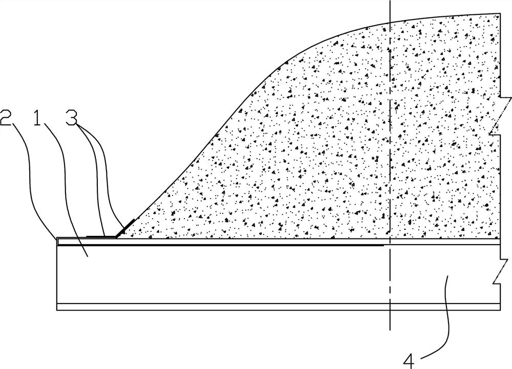
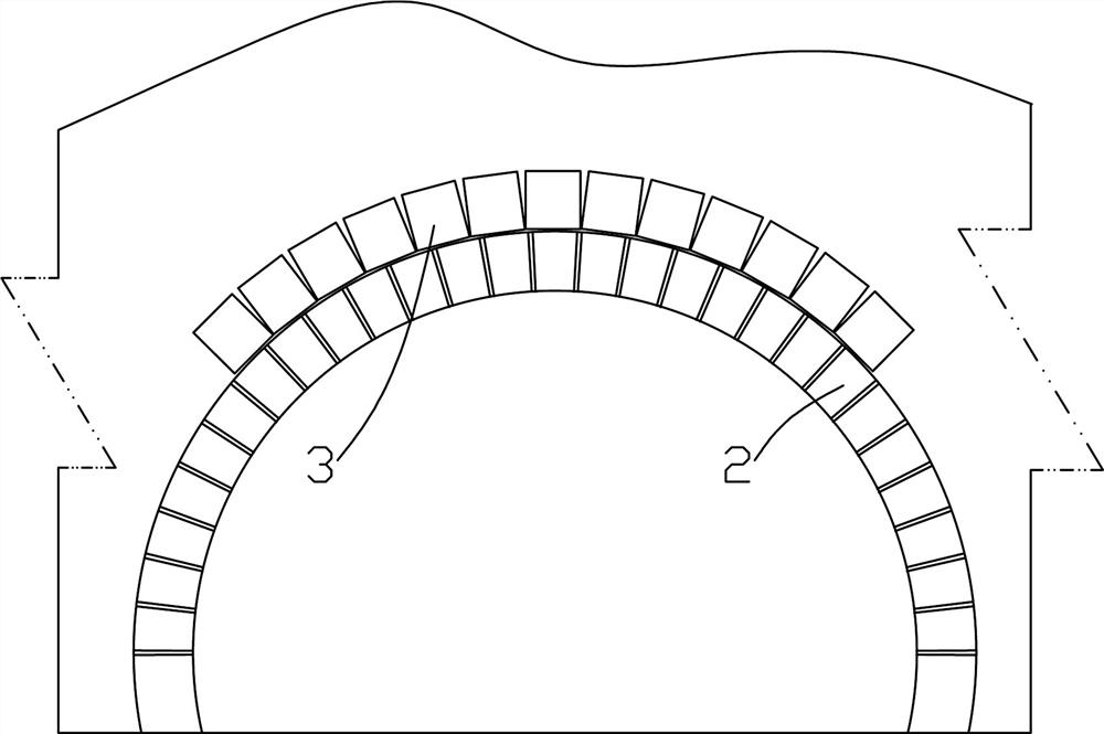
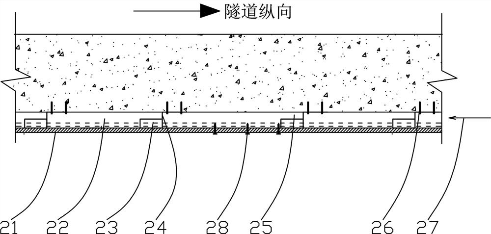
[0037] Such as Figure 1~5 Among them, a functional structure for the entrance of a tunnel. A panel structure 2 is provided at the entrance section 1 of the tunnel. The panel layer 21 of the panel structure 2 covers the outer wall of the entrance section 1, and the panel layer 21 and the entrance section A cavity structure is formed between the concrete lining surfaces of 1, and the cavity structure communicates with the inner hole section 4. With this structure, the cavity structure achieves the effect of heat preservation and avoids the direct blowing of cold air to the concrete, thereby preventing the temperature gradient on the surface of the concrete from changing too sharply, resulting in cracks in the concrete due to uneven thermal expansion and contraction. The airflow at a higher temperature in the inner hole section 4 is directly blown into the cavity structure, so that the temperature in the cavity structure is higher than the ambient temperature, and the effect of ...

Embodiment 2

[0046] On the basis of Example 1, the preferred scheme is as Image 6 , 7 Among them, a solar heat pipe 6 is provided in the panel structure 2 on the top outside of the hole section 1, and the solar heat pipe 6 communicates with the heat exchange water storage tank 7 located in the inner hole section 4 through a circulation pipeline; the energy conversion efficiency of the solar panel is low, However, the solar heat pipe 6 has a very high efficiency of collecting solar heat, and some data show that it can reach more than 85%. The liquid medium in the solar heat pipe 6 and the heat exchange storage tank 7 in this example is preferably antifreeze. The solar heat pipe 6 is a commercially available solar heat pipe 6 .

[0047] The heat exchange storage tank 7 communicates with one or more sets of pipelines 5 in the longitudinal tubes 22 and the circumferential tubes 23 of the panel structure 2 . The heat collected by the solar heat pipe 6 can be stored in the heat exchange stor...

Embodiment 3

[0054] On the basis of Examples 1 and 2, the preferred scheme is as Figure 8 , 9 Among them, a plurality of consecutively arranged reflective rings 10 are provided near the opening section 1 and the inner section 4 of the tunnel. The reflective rings 10 are ring-shaped structures, and a reflective ring approximately perpendicular to the axis of the tunnel is provided on the side away from the opening. The reflective surface is provided with reflective paint, reflective film or reflective coating. With this structure, the driver can be reminded at the position close to the opening section 1 that he is close to the exit and should pay attention to safety. In this example, the outer edge of the reflective ring 10 is provided with a folded fixing piece, which is connected with the longitudinal tube 22 or the circumferential tube 23 by self-tapping screws 28 . As far as possible, it should be installed at the position where the circumferential pipe 23 is provided. Further prefe...


PUM


Abstract

The invention provides a functional structure for a tunnel opening. A panel structure is arranged at the opening section of the tunnel. The panel layer of the panel structure covers the outer wall of the opening section, and the surface of the concrete lining between the panel layer and the opening section A cavity structure is formed between them, and the cavity structure communicates with the inner hole section. A plurality of longitudinal pipes along the longitudinal direction of the tunnel are fixed on the surface of the concrete lining, and ring pipes are arranged between the longitudinal pipes; a flow gap is provided between the ring pipes and the surface of the concrete lining; between the longitudinal pipes and the ring A panel layer is fixed on the pipe. By adopting the structure of longitudinal tube, circumferential tube and panel layer, a layer of cavity structure can be formed on the surface of the concrete lining. The cavity structure can prevent the surface of the concrete lining from being directly blown by the wind, and can use the cavity structure to form a temperature buffer. Thereby reducing the temperature gradient change of the concrete lining structure and protecting the surface of the concrete lining.

Description

technical field [0001] The invention relates to the field of railway and highway tunnel construction, in particular to a functional structure for tunnel openings with the functions of heat preservation, prompting, visual adjustment and decoration. Background technique [0002] With the development of the expressway, it began to extend to the northern alpine region, and the number of tunnel projects in the alpine region began to increase year by year. Tunnel insulation is the top priority of tunnel construction in the northern alpine region. The large temperature difference between day and night makes the concrete lining surface of the tunnel mouth prone to cracks, causing safety hazards and unsightly appearance. Power supply is relatively difficult in tunnel engineering in alpine regions. When coming out of the tunnel, the driver is prone to "flash blindness" due to the sharp change of light inside and outside the tunnel, and safety accidents are prone to occur. Chinese pat...

Claims


Application Information

Patent Timeline
Patent Type & Authority Patents(China)
IPC IPC(8): E21D9/14E21D11/38F21S9/03F21V23/02F21V33/00F21W131/103F21Y115/10
CPCE21D9/14E21D11/38F21S9/035F21V23/023F21V33/006F21W2131/103F21Y2115/10Y02B20/72
Inventor 唐祖阳陈林李永兴崔栓栓唐健
Owner CCCC SECOND HARBOR ENG
Learn More