Multifunctional crawling machine
A crawling machine and multi-functional technology, applied in the field of multi-functional crawling machines, can solve the problems of high safety and stability, the inability of treadmills to perform crawling exercises, and large space occupation, so as to achieve the effect of ensuring coordination and flexibility
- Summary
- Abstract
- Description
- Claims
- Application Information
AI Technical Summary
Problems solved by technology
Method used
Image
Examples
Embodiment 1
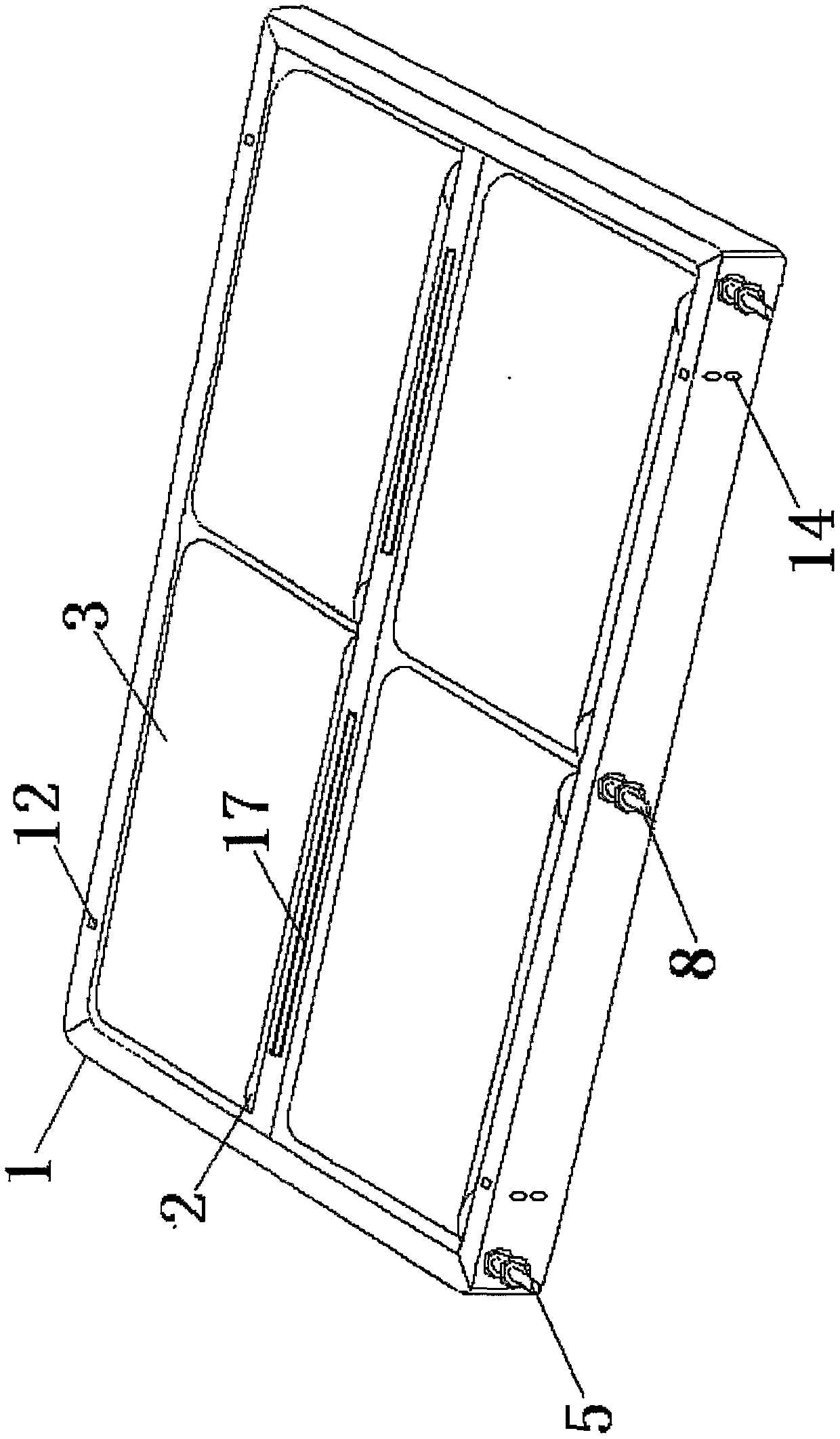
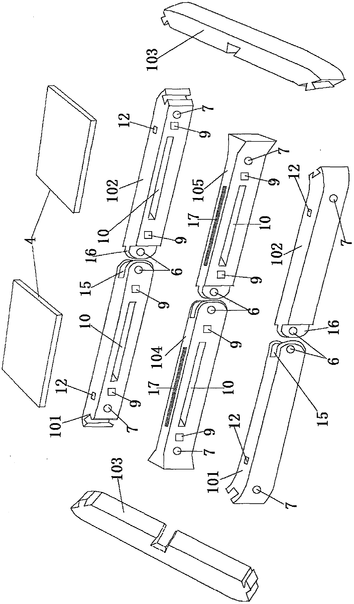
[0036] Embodiment one: if figure 1 , 2 , 5, the technical solution adopted by the present invention is: a multifunctional crawling machine, used for crawling exercise, including a treadmill 1, a wheel 2, a running belt 3, a pedal 4, characterized in that the running Platform 1 is made up of side beam 1 101 on the left and right sides, side beam 2 102 and side beam 3 103 at the front and rear ends, and middle beam 1 104 and middle beam 2 105 that divide the running platform into two parts in the length direction. A running platform 1 with a frame structure composed of end-to-end mortise-and-mortise joints or mutually hinged joints, in which the front end of side beam 1 101 and the rear end of side beam 2 102 are respectively connected to the trapezoidal mortise and groove at both ends of side beam 3 through the trapezoidal tenon at the end. The rear end of side beam one 101 and the front end of side beam two 102 and the rear end of middle beam one 104 and the front end of midd...
Embodiment 2
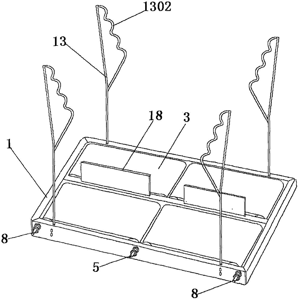
[0042] Embodiment two: if figure 2 , 3 , 5, and 6, on the basis of the technical solution of Embodiment 1, further, the technical solution of the present invention also includes armrest frame 14, dividing plate 18, and the technical solution does not need to install A-shaped frame legs 11, Place the running platform 1 directly on the ground, and install the armrest frame 13 and the partition plate 18. It is suitable for middle-aged and elderly people and women to carry out two-person running exercises. The second technical solution adopted is: it is characterized in that the described Four square armrest frame mounting holes 12 are respectively opened on the front end upper plane of side beam one 101 and the rear end upper plane of side beam two 102, and armrest frame 13 is inserted in the armrest frame mounting hole four 12. Frame 13 comprises Y-shaped frame bar 1301, and the hockey stick-shaped handrail 1302 is obliquely welded between the upper end of Y-shaped frame bar 1...
Embodiment 3
[0044] Embodiment three: as figure 2 , 4 , 5, 6, and 7, on the basis of the technical solution of embodiment two, further, the technical solution of the present invention also includes A-shaped frame legs 11, and this technical solution needs to install A-shaped frame legs 11, and the treadmill 1. Bend downwards to form two symmetrical inclined running surfaces, which are suitable for young and middle-aged people to run for two people. The third technical solution is: it is characterized in that the distance between the nut two 502 and the nut three 503 An A-shaped frame leg 11 is movable on the rotating shaft, a sleeve 1101 is welded on the top of the A-shaped frame leg 11, a crossbeam 1103 is welded between the two fork legs 1102, and a foot plate 1104 is welded on the bottom of the two fork legs 1102. Nut three 503 can fix A-shaped frame leg 11, loosen nut three 503, A-shaped frame leg 11 can rotate around rotating shaft one 5 and rotating shaft two 8.
[0045] The A-sha...
PUM
| Property | Measurement | Unit |
|---|---|---|
| Width | aaaaa | aaaaa |
| Length | aaaaa | aaaaa |
| Thickness | aaaaa | aaaaa |
Abstract
Description
Claims
Application Information
 - R&D
- Intellectual Property
- Life Sciences
- Materials
- Tech Scout
- Unparalleled Data Quality
- Higher Quality Content
- 60% Fewer Hallucinations
Browse by: Latest US Patents, China's latest patents, Technical Efficacy Thesaurus, Application Domain, Technology Topic, Popular Technical Reports.
© 2025 PatSnap. All rights reserved.Legal|Privacy policy|Modern Slavery Act Transparency Statement|Sitemap|About US| Contact US: help@patsnap.com


