
Pressurizing hemostatic patch for transfusion

A technology of hemostatic patch and pressure plate, which is applied in the field of medical devices, can solve the problems of restricted movement of patients and medical staff, bleeding from infusion needle holes, and short pressing time, so as to improve the healing speed, prevent bleeding, and reduce bruises

Pending Publication Date: 2020-06-02
李映辉
View PDF0 Cites 1 Cited by
  • Summary
  • Abstract
  • Description
  • Claims
  • Application Information

AI Technical Summary

Problems solved by technology

After the patient’s infusion is completed, because the infusion needle hole is difficult to coagulate quickly, the doctor asks the weak patient or non-professional relatives and friends to press the needle port. If the pressing is not in place or the pressing time is short, the infusion needle hole may continue to bleed and bruise. and security risks
However, during the process of pressing the infusion needle hole, the movement of the patient or medical staff will be restricted. If the patient is eager to relieve, wear, arrange daily necessities and luggage, the action of pressing the infusion needle hole will cause serious inconvenience

Method used


Image

  • Pressurizing hemostatic patch for transfusion
  • Pressurizing hemostatic patch for transfusion
  • Pressurizing hemostatic patch for transfusion

Examples


Embodiment 1

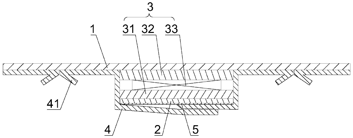
[0027] See figure 1 As shown, this embodiment provides an infusion pressurized hemostatic patch, which mainly includes a medical tape 1, a sterile anti-inflammatory block 2 and a pressurizing device 3.

[0028] The pressure device 3 includes a pressure plate 31, a pressure release plate 32, and a reset member 33. The pressure plate 31 and the pressure release plate 32 are locked to be relatively stationary by a lock structure. The reset member 33 is sandwiched between the pressure plate 31 and the pressure release plate 32. At this time, the pressurizing device 3 is in an energy storage state, and all components are made of medical materials.

[0029] The sterilization and anti-inflammatory block 2 is arranged on the outside of the pressure plate 31 and abuts against the bleeding port of the part to be hemostatic. The sterilizing and anti-inflammatory block 2 is made of medically flexible and sterile materials, which can be one or more of sterilized expanded sponge, re-foamed spong...

Embodiment 2

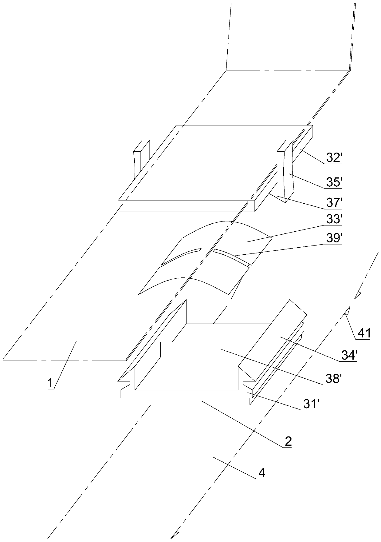
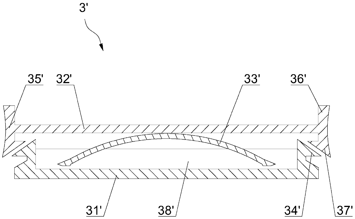
[0036] See figure 2 with 3 As shown, this embodiment provides an infusion pressurizing hemostatic patch, and the pressurizing device is further designed on the basis of Embodiment 1.

[0037] In the pressing device 3', the two sides of the pressing plate 31' protrude to form a clamping wall, the clamping wall is provided with a first hook 34', and both sides of the pressure release plate 32' are provided with decompression handles 35 ', the end of the decompression handle 35' beyond the upper surface of the release plate 32' is the pressing portion 36', and the end beyond the lower surface of the release plate 32' forms a second hook 37'. The first hook 34' and the second The hook portion 37' cooperates with the buckle to form a lock structure. After pressing the pressing portions 36' on both sides, the decompression handle 35' is elastically inclined, and the first hook portion 34' and the second hook portion 37' are separated and unlocked.

[0038] The restoring member 33' can b...

Embodiment 3

[0042] See Figure 4 with 5 As shown, this embodiment provides an infusion pressurizing hemostatic patch, and the pressurizing device is further designed on the basis of the second embodiment.

[0043] The difference from Embodiment 2 is that the resetting piece 33' here is an arched shrapnel, the dome of the arched shrapnel is fixedly connected to the pressure plate 31', and the arch edge is in contact with the pressure plate 31' and the edge is arched when stressed Deformed outwards, and the release plate 32', the decompression handle 35', and the reset piece 33' are integrally formed with medical materials, so that the setting of the limit card 38' and the limit slot 39' can be omitted, and the press pressure. The rest of the structure is the same as in the second embodiment.


PUM


Abstract

The invention discloses a pressurizing hemostatic patch for transfusion. The pressurizing hemostatic patch for transfusion comprises a medical adhesive tape, a sterilization anti-inflammatory block and a pressurizing device, wherein the pressurizing device comprises a pressurizing plate, a pressure relief plate and a resetting piece; the pressurizing plate and the pressure releasing plate are locked through a lock structure and are relatively static; the resetting piece is clamped between the pressurizing plate and the pressure releasing plate; the sterilization anti-inflammation block is arranged on the outer side of the pressurizing plate and abuts against a bleeding opening of a part to receive hemostasis; the medical adhesive tape is pasted on the outer side of the pressure relief plate and pasted on the part to receive hemostasis; and after the lock structure is unlocked, the resetting piece expands the relative distance between the pressurizing plate and the pressure relief plate, so the sterilization anti-inflammation block is provided with continuous pressing force which is applied to the bleeding opening. According to the pressurizing hemostatic patch for transfusion, thepressurizing device capable of storing energy is bound to the sterilizing anti-inflammatory block, and the pressurizing device is unlocked to generate extrusion force on the sterilizing anti-inflammatory block, so the sterilizing anti-inflammatory block is pressed at a transfusion wound; and therefore, bleeding is effectively prevented, bruise is reduced, the safety of a patient is protected, a healing speed is increased, a pressing effect can be guaranteed, and a hemostatic effect is obvious.

Description

Technical field [0001] The invention relates to the technical field of medical devices, in particular to an infusion pressurizing hemostatic patch. Background technique [0002] Intravenous infusion technology is one of the most commonly used, most direct and safest clinical treatment methods. Since the infusion needs to be injected intravenously, it is inevitable that infusion needle holes will be formed on the patient's body. After the patient's infusion is completed, because the infusion needle hole is difficult to coagulate quickly, the doctor asks the sick patient or non-professional relatives and friends to press the needle port. If the pressure is not in place or the pressing time is short, it is easy to cause continuous bleeding and bruising from the infusion needle hole And safety hazards. However, in the process of pressing the infusion needle hole, the movement of the patient or medical staff will be restricted. If the patient is eager to untie, put on, organize dail...

Claims


Application Information

Patent Timeline
Patent Type & Authority Applications(China)
IPC IPC(8): A61B17/12A61F13/02A61F13/00
CPCA61B17/12A61F13/02A61B2017/12004A61F2013/00468
Inventor 李映辉
Owner 李映辉
Learn More