


Quick Research
Generate reliable direction feasibility study reports for your R&D in just a few steps.

Technical Q&A
Discover and master advanced knowledge NOW. Basics, ideas, possibilities, all at once.

Find Solutions
As an expert in R&D theories, this can generate solutions to your technical problems instantly.

Evaluate Feasibility
Analyze your overall solution with one click, know your potential R&D risks in advance.

Monitor Landscape
Get weekly tech updates, stay abreast of the latest tech innovations and key insights.
Multifunctional closed-loop motor driver, driving device thereof and automatic device
A motor driver, multi-functional technology, applied in the direction of motor control, motor generator control, AC motor control, etc., can solve the problems of closed-loop motor driver lack of brake function, poor anti-interference performance, and difficult troubleshooting
- Summary
- Abstract
- Description
- Claims
- Application Information
AI Technical Summary
Problems solved by technology
Method used
Image

Examples
no. 1 example
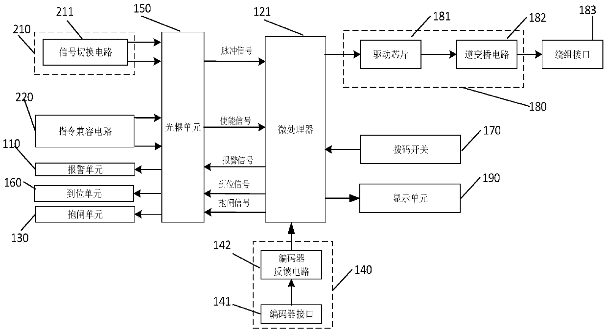
[0094] An embodiment of the present invention provides a multifunctional closed-loop motor driver. The multifunctional closed-loop motor driver mentioned in the present invention includes closed-loop stepping motor drivers, hybrid servo motor drivers, stepping servo motor drivers, low-voltage servo motor drivers, AC Servo motor drivers and other sub-categories, the multifunctional closed-loop motor drivers are used to drive motors. See figure 1, the motor driver includes a command switch switching circuit 210 , an optocoupler unit 150 , a microprocessor 121 , a drive unit 180 , a winding interface 183 , and an encoder feedback unit 140 .
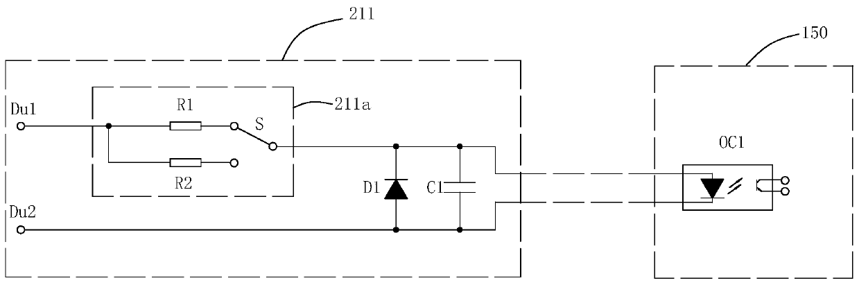
[0095] In this embodiment, the instruction switch switching circuit 210 is used for receiving instruction signals. Please continue to see figure 1 , the command switch switching circuit 210 includes at least one signal switching circuit 211, for example, the command switch switching circuit 210 includes one signal switching circuit 211, tw...
no. 2 example
[0130] Image 6 is a block diagram of the multifunctional closed-loop motor driver of the second embodiment of the present invention, Image 6 The schematic diagram with figure 1 The schematic diagrams are similar, so the same component symbols represent the same components. The main difference between this embodiment and the first embodiment is that the instruction switch switching circuit includes two signal switching circuits.
[0131] See Image 6 and Figure 7 , in this embodiment, the instruction switch switching circuit 310 includes two signal switching circuits 211, the optocoupler unit 350 includes two first optocouplers OC1, and the input of the two first optocouplers OC1 The output sides of the two first optocouplers OC1 are electrically connected to the microprocessor 121 respectively.
[0132] In this embodiment, one of the signal switching circuits 211 of the two signal switching circuits 211 ( Figure 7 The upper signal switching circuit) is used to access...
no. 3 example
[0136] Figure 8 is a block diagram of the motor driver of the third embodiment of the present invention, Figure 8 The schematic diagram with Image 6 The schematic diagrams are similar, so the same component symbols represent the same components. The main difference between this embodiment and the second embodiment is that the instruction switch switching circuit includes three signal switching circuits.
[0137] See Figure 8 and Figure 9 , in this embodiment, the instruction switch switching circuit 710 includes three signal switching circuits 211, the optocoupler unit 750 includes three first optocouplers OC1, and the inputs of the three first optocouplers OC1 The output sides of the three first optocouplers OC1 are electrically connected to the microprocessor 121 respectively.
[0138] In this embodiment, one of the signal switching circuits 211 of the three signal switching circuits 211 is used to access one of the four signals of pulse signal, direction signal, e...
PUM
 Abstract
Description
Claims
Application Information
 - R&D Engineer
- R&D Manager
- IP Professional
- Industry Leading Data Capabilities
- Powerful AI technology
- Patent DNA Extraction
Browse by: Latest US Patents, China's latest patents, Technical Efficacy Thesaurus, Application Domain, Technology Topic, Popular Technical Reports.
© 2024 PatSnap. All rights reserved.Legal|Privacy policy|Modern Slavery Act Transparency Statement|Sitemap|About US| Contact US: help@patsnap.com