
Tandem type multi-spindle machining center and numerical control machining method

A machining center, multi-spindle technology, applied in metal processing, metal processing equipment, metal processing machinery parts, etc., can solve problems such as low production efficiency, and achieve the effect of increasing output and improving production efficiency

Pending Publication Date: 2020-05-29
DONGGUAN SHARPE CNC MACHINE
View PDF0 Cites 0 Cited by
  • Summary
  • Abstract
  • Description
  • Claims
  • Application Information

AI Technical Summary

Problems solved by technology

[0003] Existing CNC machining centers use a spindle to perform drilling, tapping, and milling on a workpiece to complete complex processing of a product. A single device can only process one workpiece at a time, resulting in production low efficiency

Method used


Image

  • Tandem type multi-spindle machining center and numerical control machining method
  • Tandem type multi-spindle machining center and numerical control machining method
  • Tandem type multi-spindle machining center and numerical control machining method

Examples


Embodiment 1

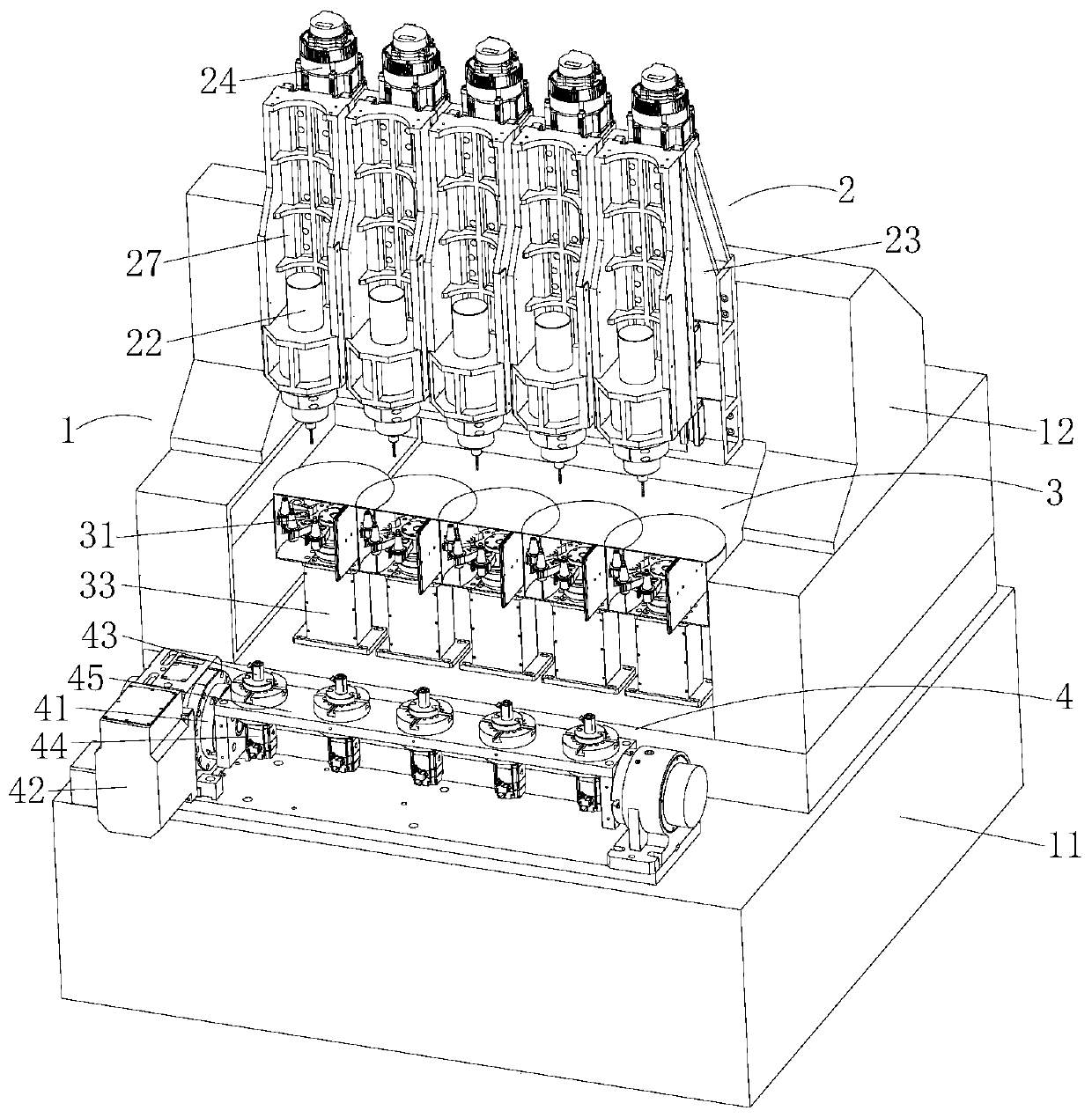
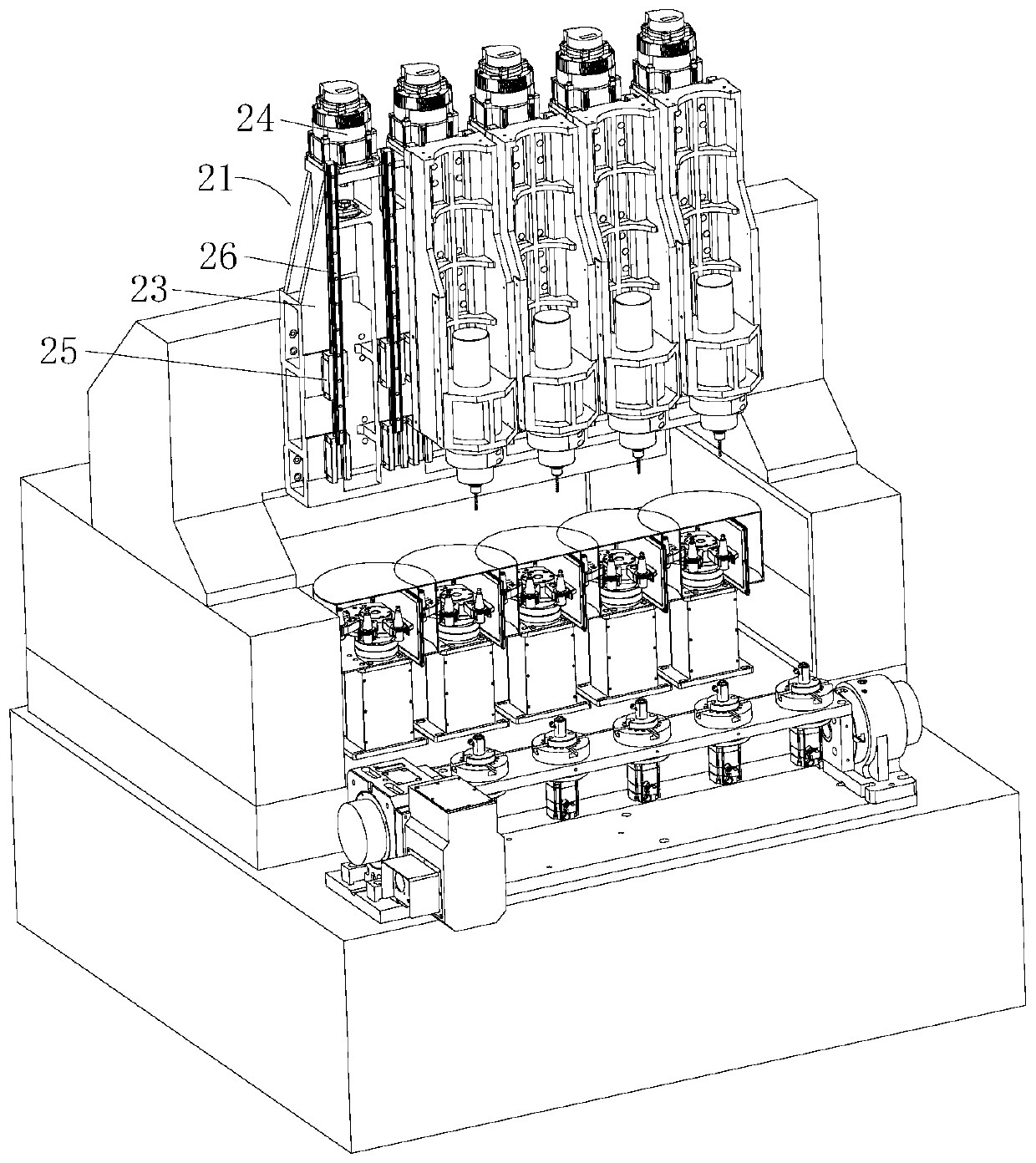
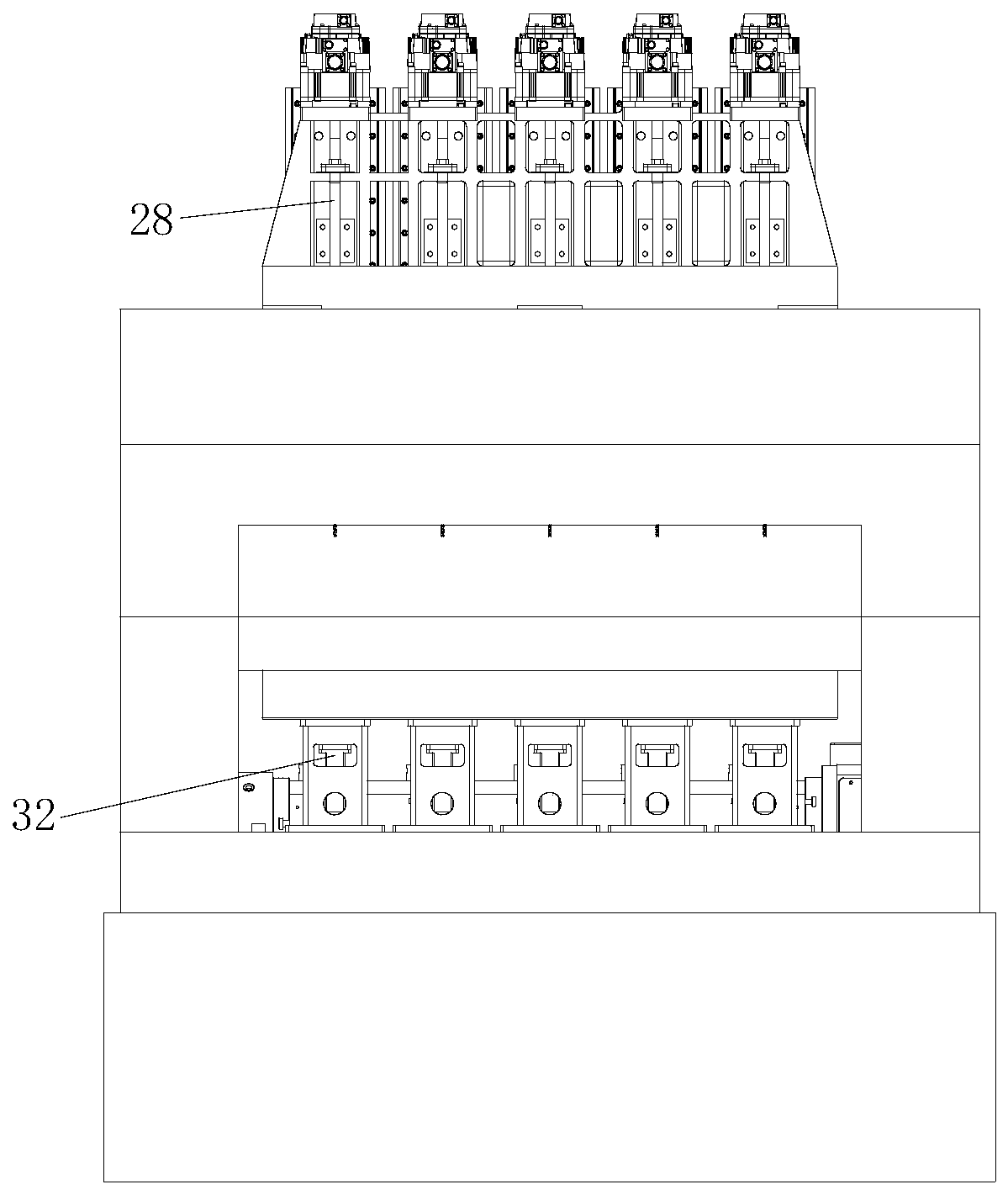
[0024] Such as Figure 1-3 As shown, a tandem multi-spindle machining center includes a frame 1, at least two spindle devices 2 installed side by side on the frame for installing fixed tools, and at least two parallel mounted on the frame 1 And with the tool magazine device 3 installed under the spindle device 2 corresponding to the spindle device 2 one-to-one, installed on the frame 1 and one-to-one with the spindle device 2, it is applied to the work of placing workpieces Table device 4. The present invention arranges a plurality of spindle devices 2, each spindle device 2 corresponds to a tool magazine device 3 and a workbench device 4, each spindle device 2 operates independently, and the equipment can process multiple workpieces at a time. After the machining process, the entire series-connected spindle device 2 can perform tool changing actions at the same time, effectively improving the output per unit time of the equipment and greatly improving production efficiency. ...

Embodiment 2

[0033] A kind of numerical control processing method, comprises the following steps,

[0034] (1) Place a plurality of workpieces to be processed on corresponding jigs 43 respectively, and the rotating shaft drive motor 42 drives the rotating shaft 41 to rotate to the corresponding position, driving the workpieces to reach the corresponding position and wait for processing;

[0035] (2) on each main shaft 22, according to machining requirement, corresponding tool is installed, and each longitudinal drive motor 24 drives corresponding main shaft 22 to move downwards simultaneously, and workpiece is processed simultaneously;

[0036] (3) After the processing is completed, the longitudinal drive motor 24 drives the corresponding main shaft 22 to move upwards simultaneously, and multiple main shafts 22 perform tool changing actions at the same time.

[0037] The present invention uses multiple spindles 22 to simultaneously process multiple workpieces such as drilling, tapping, and...


PUM


Abstract

The invention discloses a tandem type multi-spindle machining center. The tandem type multi-spindle machining center comprises a machine frame, at least two spindle devices, at least two tool magazinedevices and workbench devices, wherein the spindle devices are arranged on the machine frame in parallel and are used for installing and fixing cutters, the tool magazine devices are arranged on themachine frame in parallel and are arranged below main shaft devices and correspond to spindle devices one by one, and the workbench devices are arranged on the machine frame in one-to-one correspondence with the spindle devices for placing workpieces. According to the tandem type multi-spindle machining center and a numerical control machining method, by arranging the plurality of spindle devices,each spindle device corresponds to a tool magazine device and a workbench device, each spindle device acts independently, equipment can machine the plurality of workpieces at a time, and after a machining process is completed, the whole spindle devices in series can perform tool changing actions at the same time, the yield in unit time of the equipment is effectively improved, and the productionefficiency is greatly improved.

Description

technical field [0001] The invention relates to the field of numerical control machining centers, in particular to a tandem multi-spindle machining center and a numerical control machining method. Background technique [0002] With the development of the country's manufacturing industry, CNC machine tools, as the mainstream product of the machine tool industry, have become the key equipment for realizing the modernization of the manufacturing industry. With the personalized, modular and fast-changing market demand, the demand for high-efficiency, high-reliability, and versatile CNC machine tools is also increasing. [0003] Existing CNC machining centers use a spindle to perform drilling, tapping, and milling on a workpiece to complete complex processing of a product. A single device can only process one workpiece at a time, resulting in production low efficiency. Contents of the invention [0004] The technical problem solved by the present invention is to provide a ser...

Claims


Application Information

Patent Timeline
IPC IPC(8): B23P23/02B23Q39/00B23Q3/157
CPCB23P23/02B23Q39/00B23Q3/157B23Q2039/006
Inventor 朱立无
Owner DONGGUAN SHARPE CNC MACHINE
Learn More