
Deodorizer

A technology of smelly head and ozone, applied in washing equipment, dry cleaning equipment, application, etc., can solve the problem of inability to decompose and remove odor components

Active Publication Date: 2020-05-26
USHIO DENKI KK
View PDF13 Cites 0 Cited by
  • Summary
  • Abstract
  • Description
  • Claims
  • Application Information

AI Technical Summary

Problems solved by technology

That is, since it is not a device that supplies ozone to the interior of the textile product, there is a problem that it cannot decompose and remove the odor components remaining in the object to be deodorized.

Method used


Image

  • Deodorizer
  • Deodorizer
  • Deodorizer

Examples


Embodiment Construction

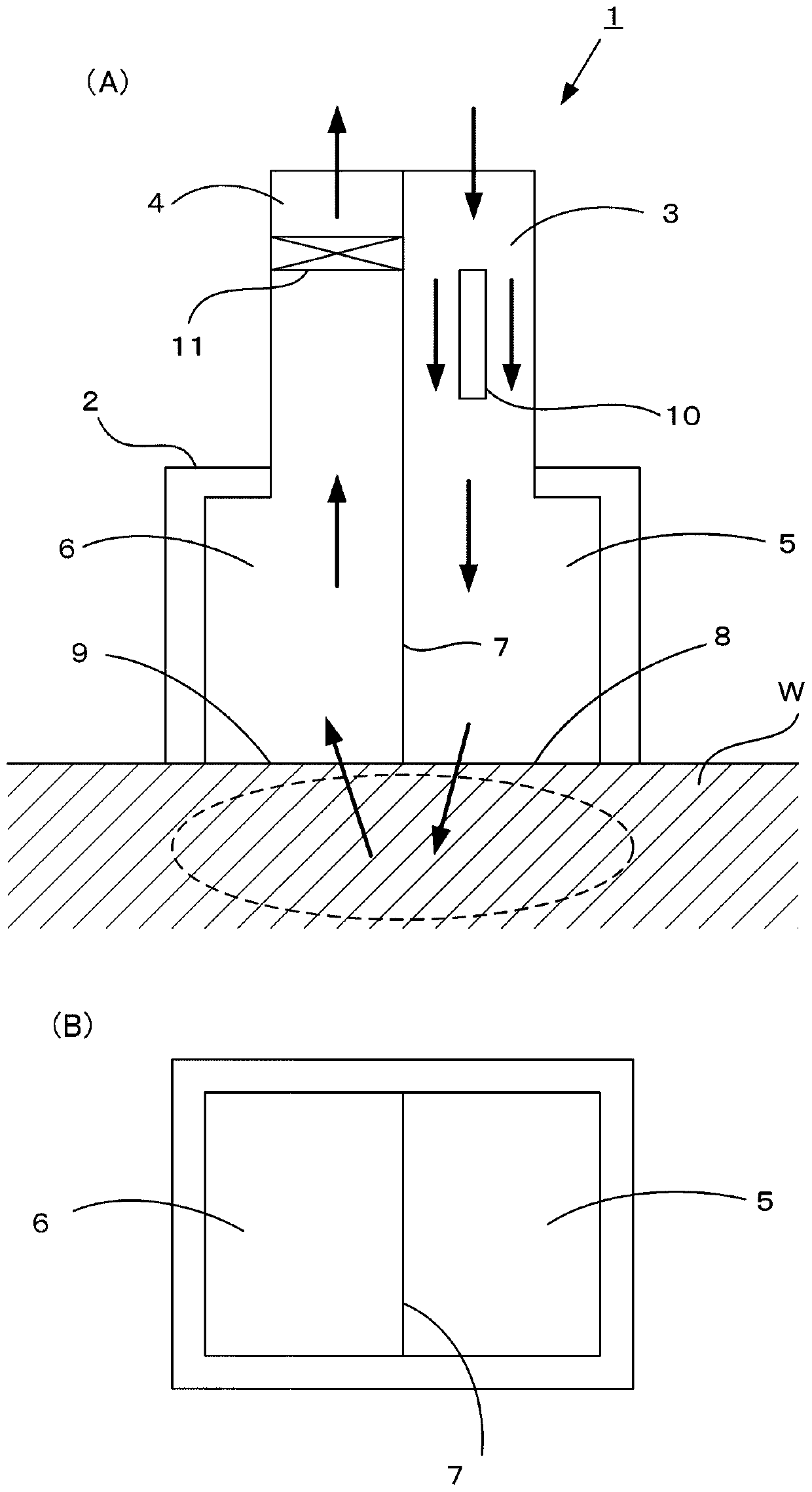
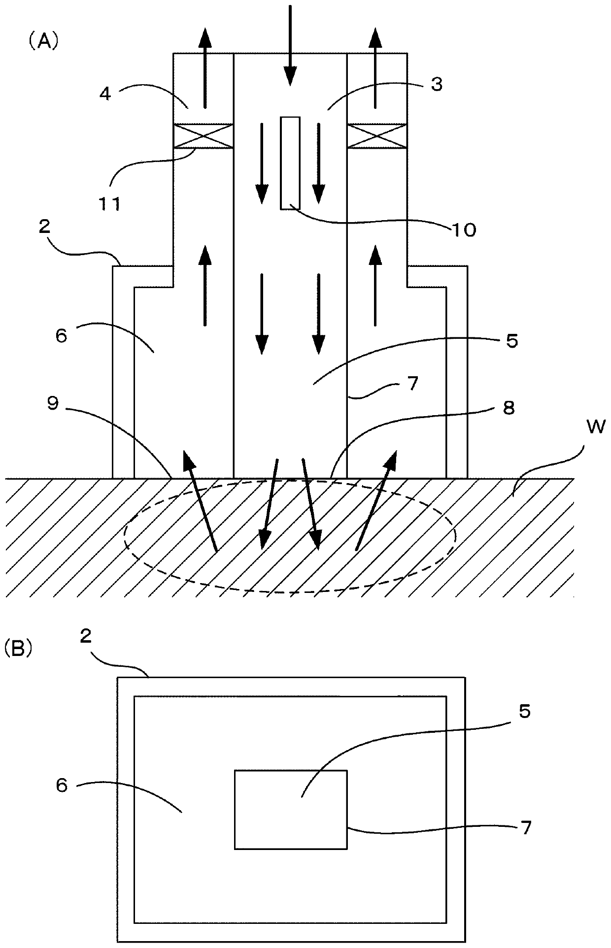
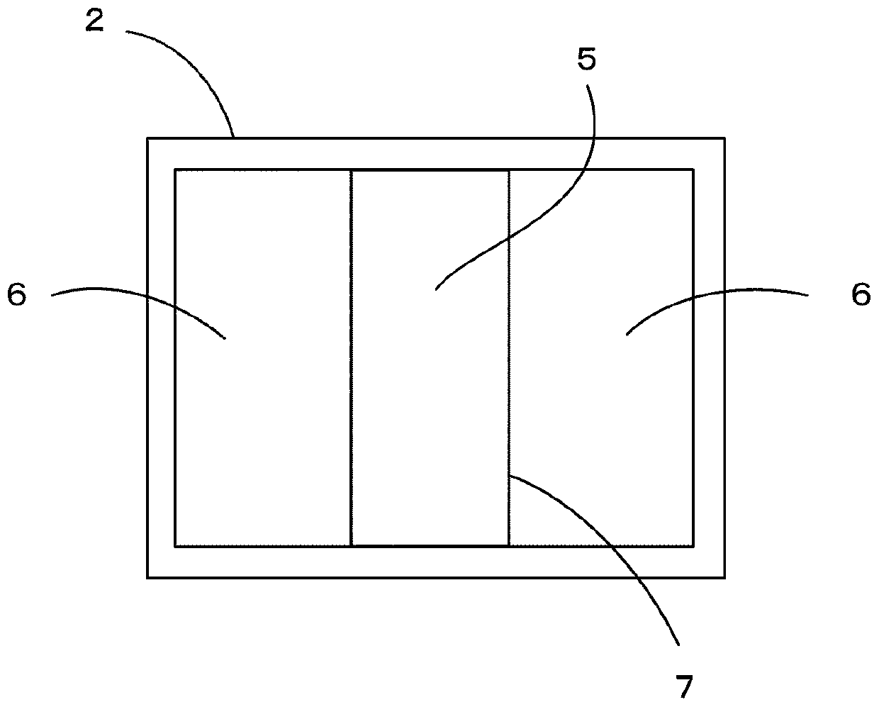
[0030] exist figure 1 3 shows a deodorizing device 1 using ozone according to the present invention. The deodorizing device 1 includes a deodorizing head 2 at the lower end and a pair of air supply passage 3 and exhaust passage 4 . The lower ends of these gas supply passages 3 are connected to the first chamber 5 , and the lower ends of the exhaust passages 4 are connected to the second chamber 6 .

[0031] Such as figure 1 As shown in (B), the first chamber 5 and the second chamber 6 are separated by a partition wall 7 , an air supply port 8 is formed at the lower end of the first chamber 5 , and an exhaust port 9 is formed at the lower end of the second chamber 6 . And the partition wall 7 extends to the lower end of the deodorizing head 2, and when the deodorizing head 2 abuts against the deodorizing parts of the deodorizing objects W such as seats and carpets, the partition wall 7 is also in contact with the deodorizing parts of the deodorizing objects W. Abut.

[003...


PUM


Abstract

The invention is to provide a deodorizer that supplies ozone-containing gas to a spot to be deodorized and deodorizes same and that can break down and remove odoriferous substances existing inside anobject to be deodorized such as a textile product. Provided is a deodorizer which includes a deodorizing bed that can be pressed against a spot to be deodorized, and is characterized in that the deodorizing bed has: a first room which has an air supply port to supply ozone-containing gas to the spot to be deodorized; a second room which is provided adjacent to the first room and has an exhaust port that suctions the gas supplied to the spot to be deodorized; and a partition that separates the first room from the second room.

Description

technical field [0001] The present invention relates to a deodorizing device for textile products, particularly a deodorizing device for decomposing odorous substances using ozone. Background technique [0002] Odor substances are easily adsorbed on fiber products such as carpets, seats of theaters or movie theaters, vehicles, and household sofas. For example, since seats in movie theaters and vehicles cannot be removed, deodorizing treatment is carried out by blowing deodorizing spray or the like, but only deodorizing the surface of the seat has little effect on deodorizing the interior of the seat. [0003] In addition, there is known an air cleaner that removes volatile organic compounds (VOC) contained in floors and walls. For example, its structure is disclosed in Japanese Unexamined Patent Publication No. 2007-152026 (Patent Document 1), and in Figure 8 shown in . [0004] exist Figure 8 Among them, the air cleaning device 20 has a cleaning head 21, and the air hea...

Claims


Application Information

Patent Timeline
Patent Type & Authority Applications(China)
IPC IPC(8): A61L9/015A61L9/20
CPCA61L9/20A61L2209/212A61L2209/134A61L2202/13A61L9/122A61L2/202A61L2202/11A61L2202/15A61L2202/26A61L2/10D06B5/24D06F43/002A61L9/015
Inventor 内藤敬祐
Owner USHIO DENKI KK
Learn More