A liquid crystal substrate glass splitting device

A liquid crystal substrate and glass technology, which is applied in the field of liquid crystal substrate glass splitting device, can solve problems such as the debris is easy to adhere to the substrate glass 4, the production efficiency of the liquid crystal display is reduced, and the surface of the platen 2 is worn, so as to reduce cleaning work, Effect of reducing wear and reducing contact

Active Publication Date: 2022-04-01
深圳市昊弘飞达科技有限公司
View PDF8 Cites 0 Cited by
  • Summary
  • Abstract
  • Description
  • Claims
  • Application Information

AI Technical Summary

Problems solved by technology

[0003] as attached Figure 7 As shown, when the fracture cutter head 8 exerts pressure on the substrate glass 4 to split, the middle part of the substrate glass 4 is stressed. Due to the existence of the cut, the bottom of the cut opens to both sides during the process of the fracture cutter head 8 pressing down, and The glass monomers on both sides of the incision are turned upwards, and the glass falls down after breaking, which may cause damage to the glass monomers. At the same time, during the turning process, the monomers at the incision are squeezed and produce huge friction with the upper surface of the platen 2, which is easy Cause the single body to wear, even break, and cause wear to the surface of the platen 2
[0004] When the substrate glass 4 splits into a single body, some debris will be produced at the fracture site, which will fall on the platen 2, and the debris cannot be cleaned in time during the fracture process. On the one hand, it is necessary to wait until the glass monomer is removed before cleaning The debris on the platen 2 is cleaned, and on the other hand, the debris is easy to adhere to the substrate glass 4, which has a great impact on the subsequent process, resulting in a decrease in the production efficiency of the liquid crystal display.

Method used


Image

  • A liquid crystal substrate glass splitting device
  • A liquid crystal substrate glass splitting device
  • A liquid crystal substrate glass splitting device

Examples


Embodiment Construction

[0023] The following will clearly and completely describe the technical solutions in the embodiments of the present invention with reference to the accompanying drawings in the embodiments of the present invention. Obviously, the described embodiments are only some, not all, embodiments of the present invention. Based on the embodiments of the present invention, all other embodiments obtained by persons of ordinary skill in the art without making creative efforts belong to the protection scope of the present invention.

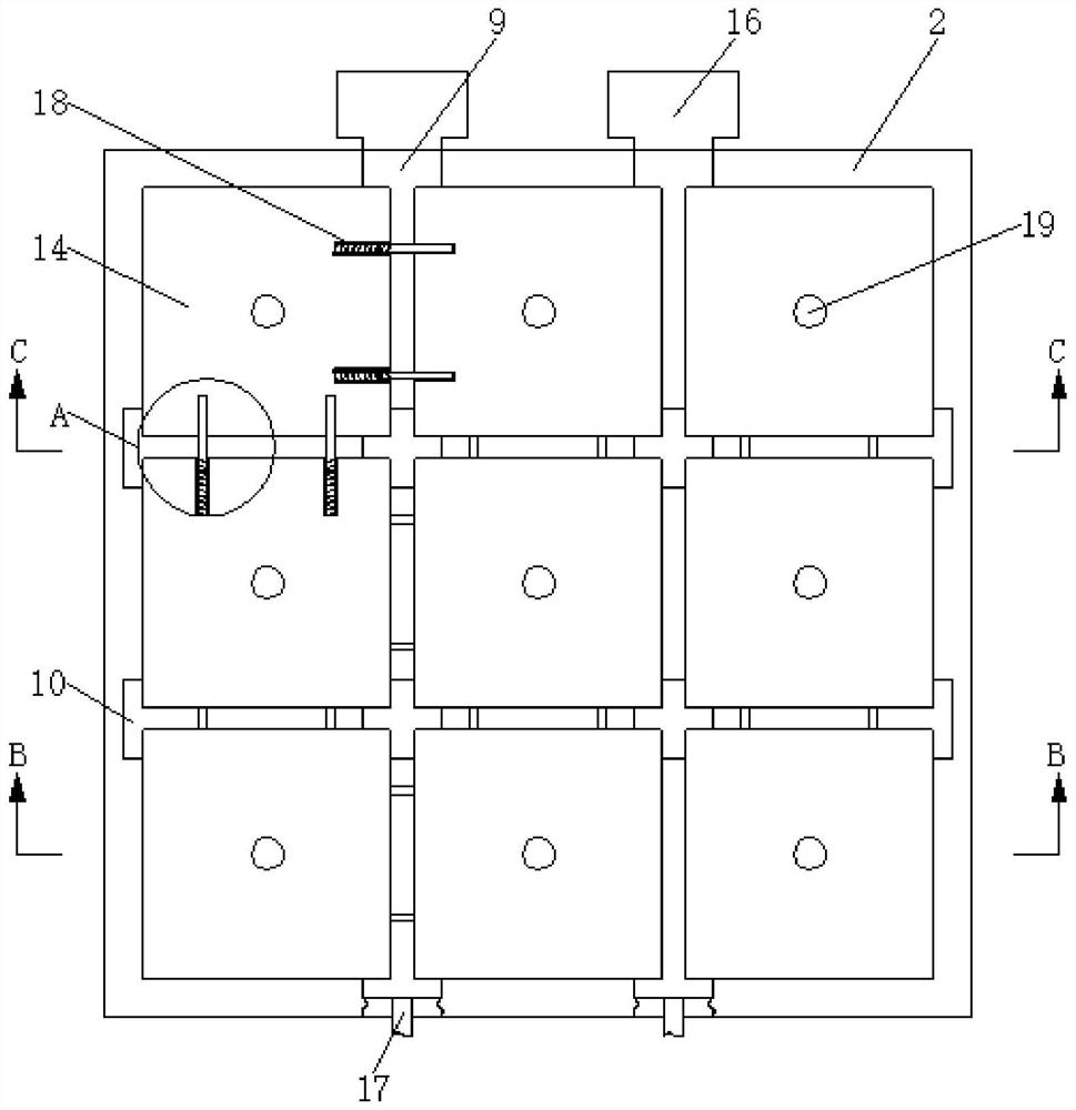
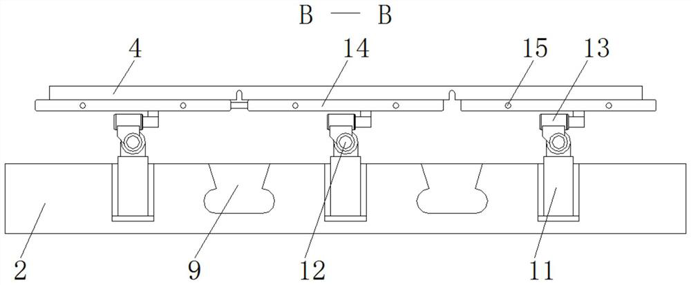
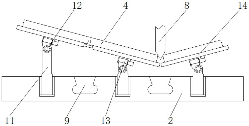
[0024] see Figure 1-5 , a glass splitting device for a liquid crystal substrate, comprising a platen 2 and a fracture cutter head 8, two symmetrically distributed chip-removing horizontal grooves 9 are provided in the middle of the platen 2, and vertically set on the platen 2 and the chip-removing horizontal groove 9 There are two symmetrically distributed chip removal vertical grooves 10, and the air pressure expansion rod 11 is evenly and fixedly installed ...


PUM


Abstract

The invention relates to the technical field of mechanical equipment, and discloses a glass splitting device for a liquid crystal substrate, which includes a platen and a breaking cutter head, and two symmetrically distributed horizontal chip removal grooves are opened in the middle of the platen. Through the setting of the monomer support platform, each glass monomer on the substrate glass is individually supported and fixed, so that when the fracture cutter head splits the substrate glass, it can follow the downward pressure of the fracture cutter head, and the substrate glass on both sides of the cut can be Rotate at a certain angle to reduce the pressure on the substrate glass on both sides of the incision when the broken cutter head is pressed down, reduce the breakage rate caused by compression, and reduce the instantaneous friction between the substrate glass and the single support platform, reducing both The wear of the contact surface, at the same time, through the setting of the connecting hole and the electromagnetic connection device, the single support platform is connected in pairs, so that when turning over, the consistency of the movement of the single support platform and the flatness of the surface of the single support platform are improved. Safety of substrate glass.

Description

technical field [0001] The invention relates to the technical field of mechanical equipment, in particular to a liquid crystal substrate glass splitting device. Background technique [0002] In the manufacture of liquid crystal displays, in order to improve production efficiency, reduce manufacturing costs, and form large-scale mass production, multiple liquid crystal displays are often produced on a larger glass, and there are multiple groups of liquid crystals on the glass after silk screen printing. For the unit of the display, these small units must be divided to perform liquid crystal perfusion, and the cutting process is to split the whole box of glass into a monomer of the liquid crystal display. The cutting process is divided into two processes: cutting and splitting. The cutter wheel forms a slit with a certain depth and width on the glass, and then splits the cut glass with a splitter. The principle of the splitter is as attached Image 6 As shown, the substrate gl...

Claims


Application Information

Patent Timeline
Patent Type & Authority Patents(China)
IPC IPC(8): C03B33/02
CPCC03B33/02
Inventor 秦绪祥
Owner 深圳市昊弘飞达科技有限公司
Why Eureka
Try Eureka