
Miniature high-speed optical fiber embedded centrifugal overload and vibration composite testing device

A test device and embedded technology, which is applied in vibration test, measuring device, machine/structural component test, etc., can solve the problems of large size, large installation space requirement, and large number of optical fiber channels, etc., to achieve small size and reduce occupancy The effect of less space and less signal connection lines

Pending Publication Date: 2020-05-22
GENERAL ENG RES INST CHINA ACAD OF ENG PHYSICS
View PDF0 Cites 3 Cited by
  • Summary
  • Abstract
  • Description
  • Claims
  • Application Information

AI Technical Summary

Problems solved by technology

This method has certain disadvantages: 1. The integrated desktop instrument is usually large in size, mostly in the 2U / 3U / 4U chassis mode, and requires a large installation space in the centrifuge instrument cabin. For the centrifuge instrument cabin with limited space, in When multiple sets of instruments need to be arranged, there are difficulties in the installation and layout of the instruments; 2. In the case of using multiple test instruments, the problem of synchronous signal acquisition of each instrument is more obvious
It is usually required that the acquisition of the overload acceleration signal and the vibration acceleration must be synchronized. Usually, the centrifugal overload signal and the vibration acceleration signal are completed by two sets of different instruments during the test. It is difficult to synchronize the signal acquisition of the two sets of instruments during the test.
3. The traditional fiber-to-Ethernet method uses two multi-mode optical fibers to complete the functions of receiving RX and sending TX, which takes up a large number of optical fiber channels and wastes the limited smooth ring resources of the centrifuge.

Method used


Image

  • Miniature high-speed optical fiber embedded centrifugal overload and vibration composite testing device
  • Miniature high-speed optical fiber embedded centrifugal overload and vibration composite testing device
  • Miniature high-speed optical fiber embedded centrifugal overload and vibration composite testing device

Examples


Embodiment Construction

[0038] The present invention will be further described below in conjunction with accompanying drawing:

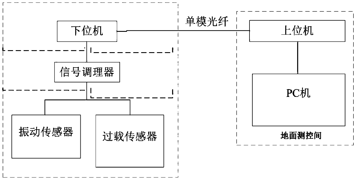
[0039] Such as figure 1 as shown,

[0040] A miniaturized high-speed optical fiber embedded centrifugal overload and vibration composite test device, including:

[0041] Vibration sensor; the vibration sensor is used to pick up the structural vibration signal of the test piece; the vibration sensor adopts a general-purpose ICP vibration acceleration sensor, the driving current is 2mA-20mA, and the power supply voltage is DC 18V-20V, which is used to pick up the structural vibration response signal of the test piece ;

[0042]The overload sensor 4; the overload sensor 4 is used for picking up the centrifugal overload signal; the vibration sensor and the overload sensor 4 are installed on the tested test piece;

[0043] Signal conditioner 3; the signal conditioner 3 is installed in the centrifuge basket and rotates together with the centrifuge basket, and the signal condit...


PUM


Abstract

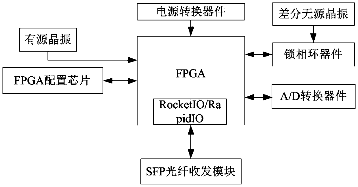
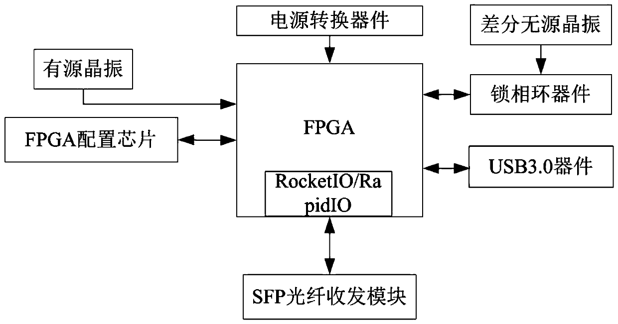
The invention discloses a miniature high-speed optical fiber embedded centrifugal overload and vibration composite testing device. The device adopts an upper computer and lower computer optical fiberhigh-speed direct connection communication mode, and a lower computer adopts a miniaturized embedded hardware circuit to realize the synchronous data acquisition of multiple centrifugal field overloadsignals and multiple vibration signals, codes and packages the data, and then directly and real-timely uploads the data to an upper computer via a high speed optical fiber and transfers the data to aPC for data storage and analysis processing. According to the device, by a high-speed optical fiber upper and lower computer direct interconnection mode, the use of a centrifuge instrument cabin anda ground network switch is omitted, a network debugging link is reduced, and the test preparation time is saved. The device realizes the synchronous acquisition of multiple overload signals and multiple vibration signals in a centrifugal vibration composite environment, realizes the synchronous high-precision acquisition of the vibration acceleration and centrifugal overload acceleration signals,and is more beneficial to the subsequent test data analysis and processing.

Description

technical field [0001] The invention belongs to the technical field of centrifugal vibration composite test, in particular to a miniaturized high-speed optical fiber embedded centrifugal overload and vibration composite test device. Background technique [0002] The centrifugal vibration composite test is mainly used to assess the mechanical transfer characteristics of the weapon system or related mechanical structural parts in the combined environment of centrifugal overload and vibration, and is an important environment for evaluating the functional reliability and structural effectiveness of the weapon system or related mechanical structural parts. test. The test is carried out on a centrifuge with a vibrating table system installed on the centrifuge, and the test piece is installed on the vibrating table. During the test, the centrifuge is driven to rotate at a certain overload acceleration and the vibrating table vibrates at a certain level. The parameter to be tested i...

Claims


Application Information

Patent Timeline
IPC IPC(8): G01M7/02G01M99/00G01H17/00G01P15/00G08C23/06
CPCG01M7/025G01M99/00G01H17/00G01P15/00G08C23/06
Inventor 张荣周继昆张平黄海莹毛勇建李明海李思忠
Owner GENERAL ENG RES INST CHINA ACAD OF ENG PHYSICS
Learn More