Puffed feed drying device

A drying device and technology for extruding feed, applied in drying, drying machine, drying gas arrangement and other directions, can solve problems such as affecting drying efficiency

Inactive Publication Date: 2020-05-22
ZOUPING LIBANG FEED
View PDF7 Cites 2 Cited by
  • Summary
  • Abstract
  • Description
  • Claims
  • Application Information

AI Technical Summary

Problems solved by technology

However, when the device is drying, the feed will roll in lumps in the device, which will affect the drying efficiency, so the device needs to be improved

Method used


Image

  • Puffed feed drying device
  • Puffed feed drying device
  • Puffed feed drying device

Examples


Embodiment 1

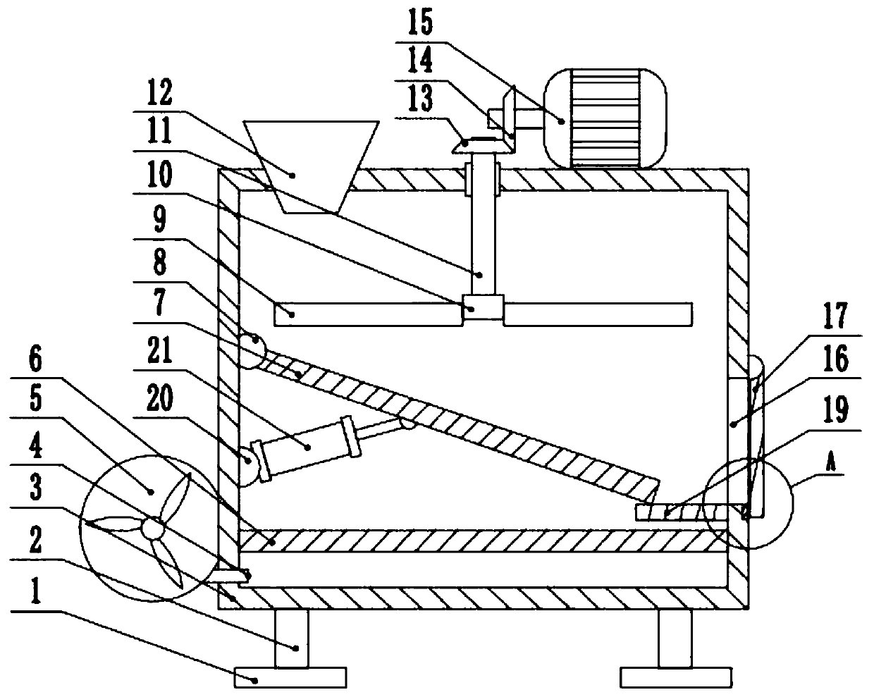
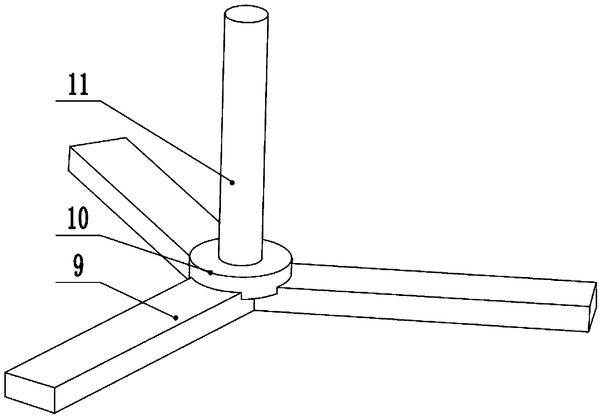
[0022] see Figure 1-3 , an extruded feed drying device, comprising a drying box 3, the left and right sides of the lower surface of the drying box 3 are provided with support columns 2, the lower end of the support column 2 is connected to the pad 1, and the left upper part of the drying box 3 is provided with There is a feed port 12, the middle part of the right side of the drying box 3 is provided with a discharge port 16, the left side wall of the drying box 3 is provided with an air pump 5, and the output end of the air pump 5 is connected to the drying box 3 through the air inlet 4 , the bottom of the drying box 3 is provided with a heating plate 6, the middle part of the left side wall of the drying box 3 is provided with a first rotating seat 8, and the first rotating seat 8 is connected to the air-permeable plate 7 in rotation, and the top of the drying box 3 Rotate and connect the rotating shaft 11, the top right side of the drying box 3 is provided with a drive moto...

Embodiment 2

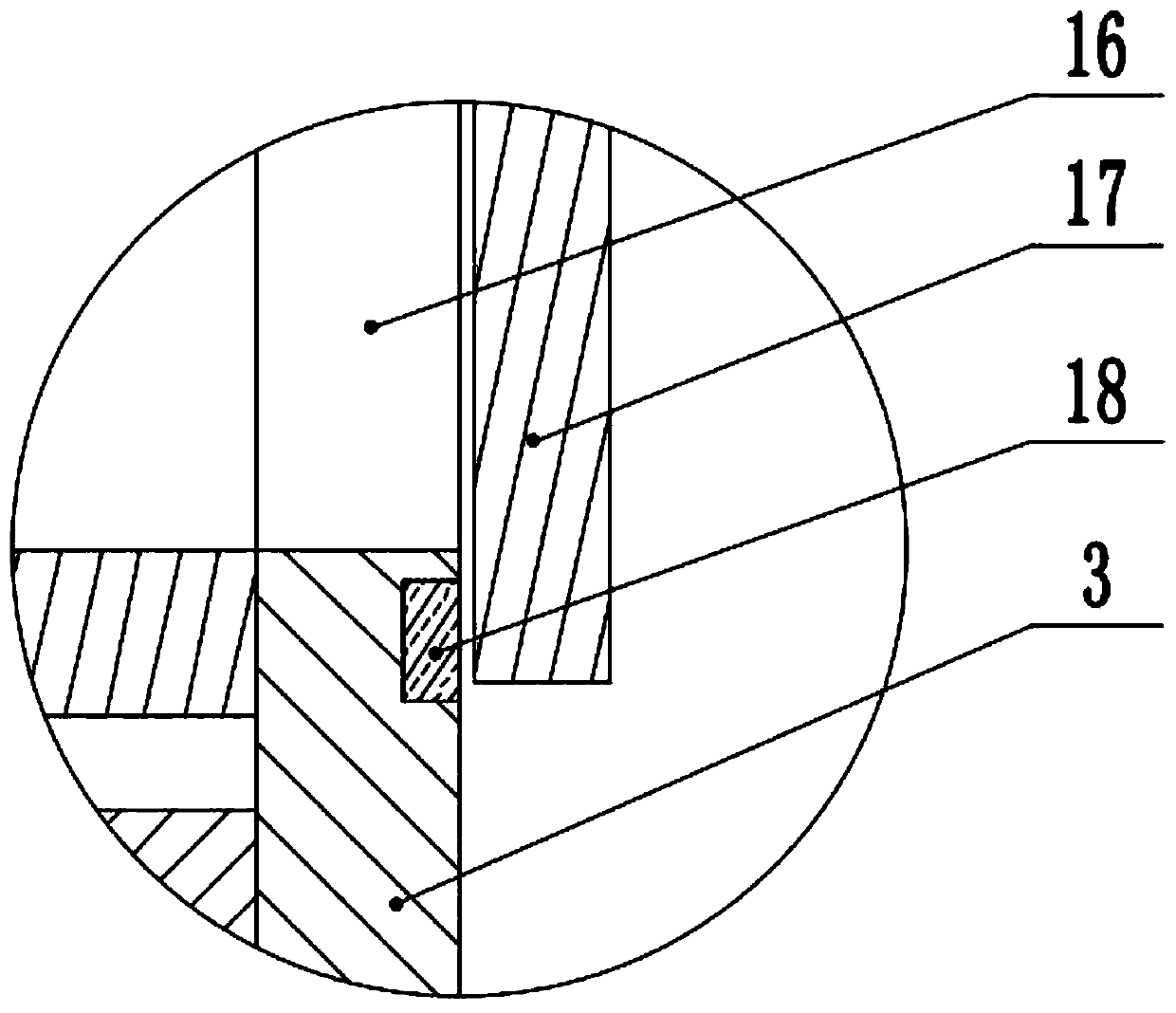
[0024] see figure 2 , the other content of this embodiment is the same as that of Embodiment 1, the difference is that: the lower part of the discharge port 16 is provided with a magnet 18, and the baffle plate 17 is made of metal. In the unstressed state, the baffle plate 17 will maintain a vertical state under the influence of gravity. At this time, the baffle plate 17 will block the discharge port 16, but in order to ensure that the baffle plate 17 can stably block the discharge port 16, the A magnet 18 is arranged at the bottom of the feed port 16, and the baffle plate 17 is made of metal, so that the baffle plate 17 is adsorbed to the column by the magnet 18, and now the baffle plate 17 can stably block the discharge port 16.

[0025] In the implementation process of the present invention, the cylinder 21 is first started, and the piston rod of the cylinder 21 stretches out, thereby pushing the air-permeable plate 7 to rotate counterclockwise. When the piston rod is full...


PUM


Abstract

The invention relates to the technical field of feed processing, and discloses a puffed feed drying device. The puffed feed drying device comprises a drying box, wherein the upper part of the left side of the drying box is provided with a feeding inlet, the middle part of the right side of the drying box is provided with a discharging outlet, the left side wall of the drying box is provided with an air pump, the output end of the air pump is connected with the drying box through an air inlet, the bottom of the drying box is provided with a heating plate, the middle part of the inner side of the left side wall of the drying box is provided with a first rotating seat, the first rotating seat is rotationally connected with a ventilating plate, the top of the drying box is rotationally connected with a rotating shaft, the lower end of the rotating shaft is provided with a fixed seat, the side edges of the fixed seat are provided with scraping plates, the upper part of the discharging portis rotationally connected with a baffle plate, and the lower part of the inner side of the left side wall of the drying box is provided with a second rotating seat. According to the puffed feed dryingdevice, the scraping plates which rotate continuously are arranged in the puffed feed drying device, so that feed is spread on the ventilating plate, the situation that feed is caked and affects thedrying effect of the feed is prevented, and the whole device is simple in structure, convenient and fast to operate, and suitable for use and popularization.

Description

technical field [0001] The invention relates to the technical field of feed processing, in particular to an extruded feed drying device. Background technique [0002] The moisture content of extruded feed is relatively high during processing. When drying with general-purpose large-scale drying equipment, although it can effectively remove the moisture on the surface of feed particles, the drying time is long, the stability is not good, and it is not easy to ripen. Thereby affecting the quality of the product. When using general-purpose small drying equipment for drying, although a certain curing effect can be achieved, it requires frequent feeding and discharging of materials, which is time-consuming and laborious, and is not easy to control. [0003] Chinese patent (notification number: CN209459360U) discloses a puffed feed drying device, which includes a drying device body and a drying device support base. The exhaust pipe is provided with a discharge port on the right s...

Claims


Application Information

Patent Timeline
Patent Type & Authority Applications(China)
IPC IPC(8): F26B11/14F26B21/00F26B25/04F26B25/02
CPCF26B11/14F26B21/001F26B21/004F26B25/02F26B25/04
Inventor 刘长征刘长顺牛海霞崔云河刘青援
Owner ZOUPING LIBANG FEED
Why Eureka
Try Eureka