Automatic clothes collecting and drying rack
A drying rack and automatic technology, which is applied in household clothes dryers, washing devices, textiles and paper making, etc., can solve the problems of blocking raindrops, clothes translocation, and the inability to realize the function of automatic drying again, achieving good drying and convenient spacing Effect
- Summary
- Abstract
- Description
- Claims
- Application Information
AI Technical Summary
Problems solved by technology
Method used
Image
Examples
Embodiment 1
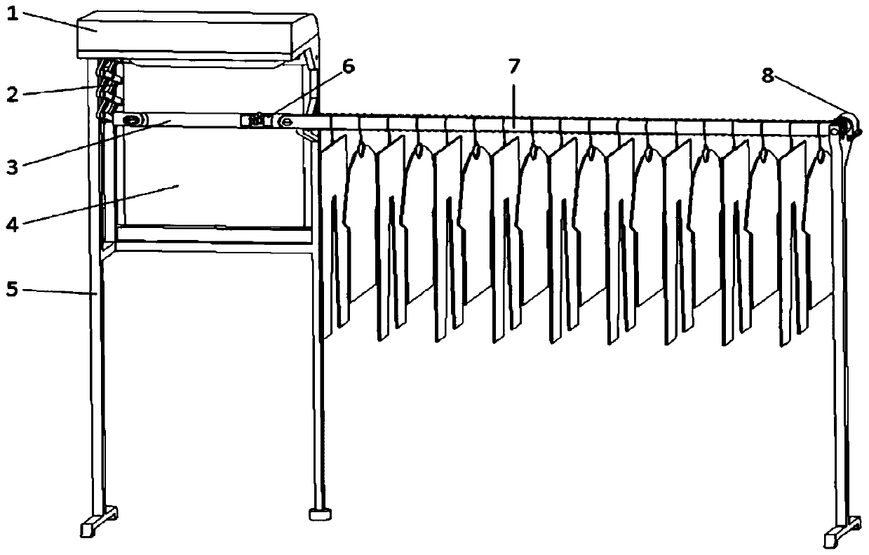
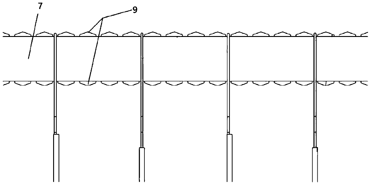
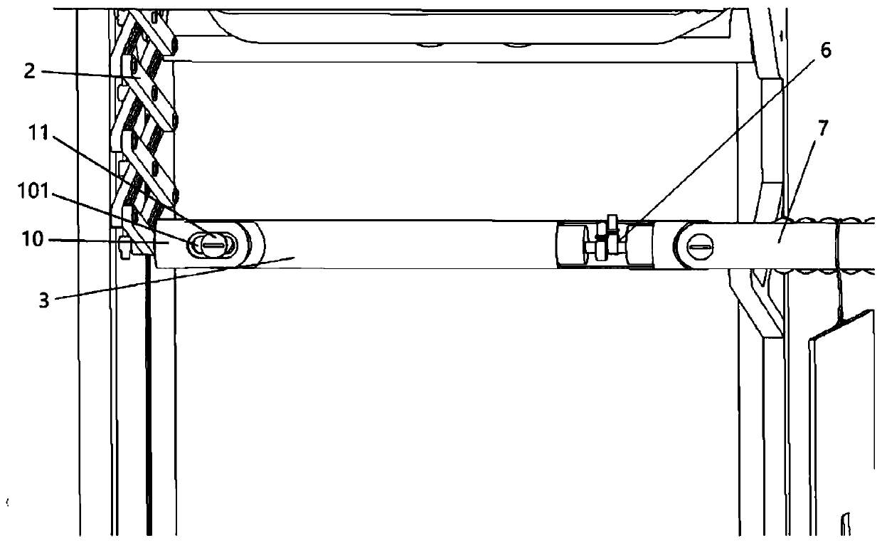
[0034] Such as figure 1 As shown, an automatic retractable drying rack includes a frame body 5, a control box 1, a lifting device 2, a storage rod 3, and a clothes drying rod 7. In this embodiment, the frame body 5 is divided into two parts, left and right. The storage area is used to store clothes to prevent them from being wet by rain, and the drying area on the right is used to dry the clothes. The storage rod 3 and the clothes drying rod 7 are both installed on the frame body 5, the lifting device 2 and the storage rod 3 are installed in the storage area, and the clothes drying rod 7 is installed in the drying area. Specifically, the clothes drying rod 7 is a long rod, both ends of which are fixedly connected with the frame 5, and a conveying device is provided on the clothes drying rod 7 for conveying the clothes hanging on the clothes rod 7. The storage rod 3 is a short rod, one end of which is hinged to the clothes drying rod 7, and the other end is connected to the lift...
Embodiment 2
[0041] This embodiment is similar to Embodiment 1, but the difference is that in this embodiment, a clothing distributing mechanism 6 is added, such as image 3 , 5 As shown, the clothes distributing mechanism 6 is a coaxial double cam structure, which is arranged in the side of the storage rod 3 close to the clothes drying rod 7. It includes a front cam 61, a rear cam 62, a front push rod 63, a rear push rod 64, and a drive A shaft 69 and a first drive motor 65. The first drive motor 65 is electrically connected to the control chip. The first drive motor 65 is connected to the drive shaft 69. The front cam 61 and the rear cam 62 are respectively connected to the drive shaft 69 on the register bar 3. Two guide holes are provided, and the front push rod 63 and the rear push rod 64 are respectively inserted into the guide holes, and the front push rod 63 and the rear push rod 64 can slide up and down along the axis of the guide hole. The end of the front push rod 63 and the front ...
Embodiment 3
[0046] This embodiment is similar to Embodiment 1 or 2, but the difference is that in this embodiment, the control box 1 is installed on the upper part of the storage area, and the storage area is provided with a rain shield 4, such as Image 6 As shown, the rain-shielding mechanism 4 includes a rolling tube 41, a guide rod 44, a third drive motor, and a rolling blind 43. One end of the rolling screen 43 is connected to the rolling tube 41, and the other end is connected to the guide rod 44. The frame body 5 is provided with a guide groove. 42, the guide rod 44 is embedded in the guide groove 42, the third drive motor is connected to the roll tube 41, the roll tube 41 is arranged on the upper part of the frame 5, and the third drive motor is electrically connected to the control chip. The control box 1 is installed on the upper part of the storage area after being waterproof designed to play a role in shielding the rainwater above. When performing the action of collecting clothes...
PUM
 Abstract
Description
Claims
Application Information
 - R&D
- Intellectual Property
- Life Sciences
- Materials
- Tech Scout
- Unparalleled Data Quality
- Higher Quality Content
- 60% Fewer Hallucinations
Browse by: Latest US Patents, China's latest patents, Technical Efficacy Thesaurus, Application Domain, Technology Topic, Popular Technical Reports.
© 2025 PatSnap. All rights reserved.Legal|Privacy policy|Modern Slavery Act Transparency Statement|Sitemap|About US| Contact US: help@patsnap.com


