Boiler convection heating surface vibratory-hitting type deashing device and vibratory-hitting method

A soot cleaning device and heating surface technology, which is applied to combustion methods, solid residue removal, lighting and heating equipment, etc., can solve problems such as inability to clean up in time, difficult ash cleaning, increased heat loss, etc., and achieve compact structure and airtight performance Good, fast response effect

Pending Publication Date: 2020-05-19
上海工业锅炉(无锡)有限公司
View PDF0 Cites 1 Cited by
  • Summary
  • Abstract
  • Description
  • Claims
  • Application Information

AI Technical Summary

Problems solved by technology

[0002] At present, as my country's boilers are intensifying various energy-saving and environmental protection efforts, many regions are using more and more non-standard fuels, including many biomass fuels that are slowly and gradually promoted in various regions; considering the tail of biomass boilers It is difficult to clean the dust on the heating surface. Conventional compressed air or shock wave cannot be used to clean it in time, and steam soot blowing will increase additional heat loss.

Method used


Image

  • Boiler convection heating surface vibratory-hitting type deashing device and vibratory-hitting method
  • Boiler convection heating surface vibratory-hitting type deashing device and vibratory-hitting method
  • Boiler convection heating surface vibratory-hitting type deashing device and vibratory-hitting method

Examples


Embodiment Construction

[0034] The specific implementation manner of the present invention will be described below in conjunction with the accompanying drawings.

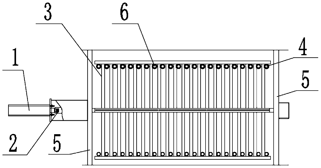
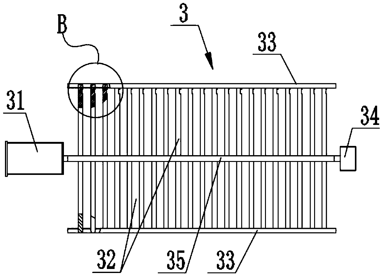
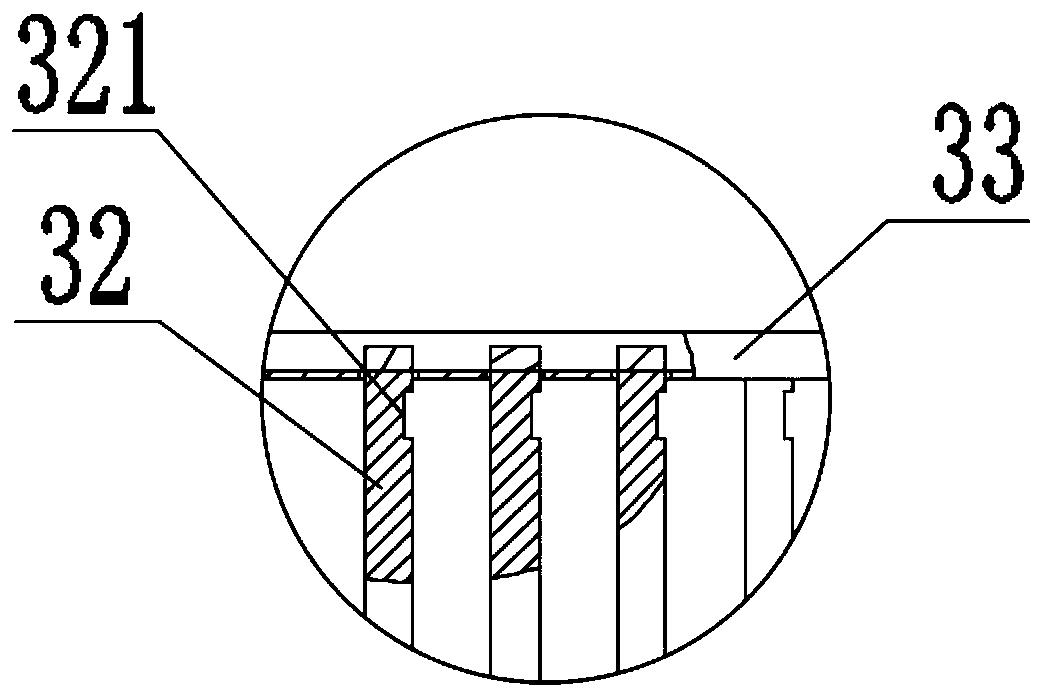
[0035] Such as Figure 1-Figure 3 As shown, the boiler convection heating surface rapping soot cleaning device of the present embodiment includes a rapping support 3, which is welded into an integral frame structure, and the middle part is provided with a support shaft 35 with one end connected to the vibrating device. 35 is provided with a plurality of vertical rods 32 at intervals in the axial direction, and the plurality of vertical rods 32 are arranged symmetrically with the support shaft 35 as the axis. Two hanging rods 33 hang the rapping support 3 on the tube bundle 4 on the heating surface of the boiler, so that each vertical rod 32 is in contact with the tube bundle 4 on the heating surface of the boiler.

[0036] The two ends of the support shaft 35 are respectively connected to the guard plates 5 at both ends of the heating sur...


PUM


Abstract

The invention relates to a boiler convection heating surface vibratory-hitting type deashing device and a vibratory-hitting method. The boiler convection heating surface vibratory-hitting type deashing device comprises a vibratory-hitting bracket which is welded as an integrated frame structure; the middle part of the vibratory-hitting bracket comprises a bracket shaft; one end of the vibratory-hitting bracket is connected with a vibrating device; the bracket shaft is provided with a plurality of vertical rods in spaced manner in the axial direction; the plurality of vertical rods are symmetrically arranged by taking the bracket shaft as the axis; the tail ends of the vertical rods at each side are connected with a hanging rod; the hanging rods and the bracket shaft are arranged in parallel; the two hanging rods are used for hanging the vibratory-hitting bracket on a tube bundle of a heated surface of a boiler so that each vertical rod makes contact with the tube bundle of the heated surface of the boiler. According to the boiler convection heating surface vibratory-hitting type deashing device provided by the invention, the two ends of the vibratory-hitting bracket and a protective plate are directly sealed by adopting a housing structure by means of welding; the vibrating device, the vibratory-hitting bracket and the convection tube bundle are compactly combined together, sothe boiler convection heating surface vibratory-hitting type deashing device is compact in structure, reasonable in design, good in leakproofness, convenient to maintain, safe, reliable, long in service life, wide in application range, smaller in space usage and higher in automation degree.

Description

technical field [0001] The invention relates to the technical field of rapping devices, in particular to a device for rapping and cleaning dust on a convection heating surface of a boiler and a rapping method. Background technique [0002] At present, as my country's boilers are intensifying various energy-saving and environmental protection efforts, many regions are using more and more non-standard fuels, including many biomass fuels that are slowly and gradually promoted in various regions; considering the tail of biomass boilers It is difficult to clean the dust on the heating surface. Conventional compressed air or shock wave cannot be used to clean it in time, and steam soot blowing will increase additional heat energy loss. Contents of the invention [0003] Aiming at the shortcomings of the above-mentioned existing production technology, the applicant provides a boiler convection heating surface rapping device and rapping method with reasonable structure. Compared wi...

Claims


Application Information

Patent Timeline
Patent Type & Authority Applications(China)
IPC IPC(8): F23J3/02
CPCF23J3/02
Inventor 蒋文年苏强
Owner 上海工业锅炉(无锡)有限公司
Why Eureka
Try Eureka