
Light guide structure, light-emitting assembly, light-emitting device and vehicle

A light-guiding structure and light-emitting component technology, which is applied to road vehicles, signal devices, vehicle parts, etc., can solve the problems of light efficiency reduction, achieve high energy intensity, high light efficiency and lighting effects, and avoid energy loss.

Pending Publication Date: 2020-05-19
HASCO VISION TECHNOLOGY CO LTD
View PDF0 Cites 4 Cited by
  • Summary
  • Abstract
  • Description
  • Claims
  • Application Information

AI Technical Summary

Problems solved by technology

[0005] Based on this, it is necessary to provide a light guide structure, a light-emitting component, a light-emitting device and a vehicle for the problem that the number of light sources needs to be increased to compensate for the reduction in light efficiency caused by cutting the light guide structure in traditional lamps.

Method used


Image

  • Light guide structure, light-emitting assembly, light-emitting device and vehicle
  • Light guide structure, light-emitting assembly, light-emitting device and vehicle
  • Light guide structure, light-emitting assembly, light-emitting device and vehicle

Examples


Embodiment Construction

[0048] The present invention will be further described below in conjunction with accompanying drawing.

[0049]In order to facilitate the understanding of the present invention, various embodiments of the present invention defined by the claims will be described more fully below with reference to the relevant drawings. Preferred embodiments of the invention have been shown in the drawings, which contain various specific details to facilitate that understanding but which should be regarded as exemplary only. However, the present invention can be embodied in many different forms and is not limited to the embodiments described herein. Accordingly, those of ordinary skill in the art will recognize that changes and modifications of the various embodiments described herein can be made without departing from the scope of the invention as defined in the appended claims. Also, descriptions of well-known functions and constructions may be omitted for clarity and conciseness.

[0050] ...


PUM

PropertyMeasurementUnit
angleaaaaaaaaaa

Abstract

The invention relates to a light guide structure, a light-emitting assembly, a light-emitting device and a vehicle. The light guide structure comprises a structure body, a light receiving surface, a light splitting surface, a deflection reflection surface and a light emitting surface. Light emitted by a light source outside the structure body of the light guide structure is collimated by the lightreceiving surface to form collimated light, and the collimated light is transmitted to the light splitting surface in the structure body in the approximately parallel direction, is received and reflected by a main light splitting surface to form main split light, and is received and reflected by a side light splitting surface to form side split light; the side split light is received by the deflection reflection surface on the transmission path and is further reflected to form side emission light; and the side emission light and the main split light penetrate through the light emitting surface and emit light to the outside of the structure body to form illumination. After being collimated and guided by the light guide structure, the light can be completely emitted from the preset light emitting surface to form a shape, the light cannot be freely scattered outwards, a light emitting area of 30-40 mm can be uniformly illuminated by utilizing a single light source, and the energy of thelight source can be more effectively utilized.

Description

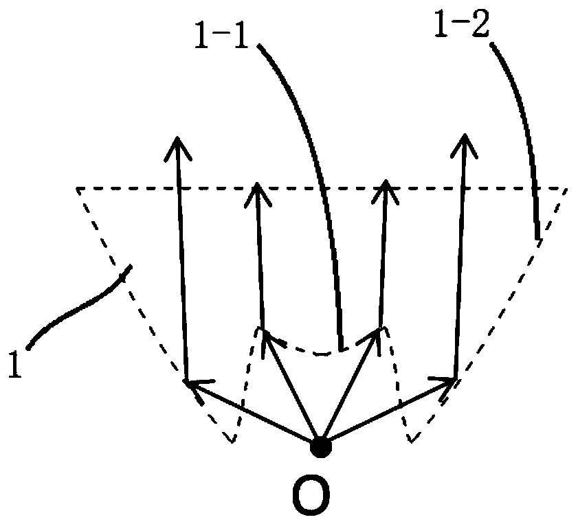
technical field [0001] The invention relates to the field of lighting structure design, in particular to a light guide structure, a light-emitting component, a light-emitting device and a vehicle. Background technique [0002] In current signal lamps, light guide structures need to be used to collimate light. Commonly used thick-walled light guide structures mainly include direct-light, reflective, and thick-walled light-guide structures combining direct light and reflection. like figure 1 Shown is a thick-walled light guide structure 1 that combines direct light and reflection, which mainly uses the direct coupling surface 1-1 and the indirect coupling surface 1-2 as the light receiving surface to collimate light: among them, the light source O emits light, and the light directed to the area where the direct coupling surface 1-1 is refracted by the direct coupling surface 1-1 is refracted and then sent out, and the light in this area is collimated; the light directed to t...

Claims


Application Information

Patent Timeline
Patent Type & Authority Applications(China)
IPC IPC(8): F21S43/241F21W107/10
CPCF21S43/241F21W2107/10F21S43/40F21S43/315
Inventor 贾震
Owner HASCO VISION TECHNOLOGY CO LTD
Learn More