Road deceleration strip

A speed bump and road technology, applied in the field of ETC, can solve the problems that the speed bump does not have the shock absorption effect, damage the vehicle, etc., and achieve the effect of reducing damage and protecting the vehicle

Active Publication Date: 2020-05-19
AEROSPACE INFORMATION
View PDF5 Cites 4 Cited by
  • Summary
  • Abstract
  • Description
  • Claims
  • Application Information

AI Technical Summary

Problems solved by technology

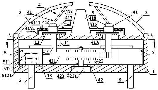
[0003] In view of this, the present invention proposes a road deceleration belt, which aims to solve the problem that the existing ETC road deceleration belt does not have the shock absorption effect and damages the vehicle

Method used


Image

  • Road deceleration strip
  • Road deceleration strip
  • Road deceleration strip

Examples


Embodiment Construction

[0022] Exemplary embodiments of the present disclosure will be described in more detail below with reference to the accompanying drawings. Although exemplary embodiments of the present disclosure are shown in the drawings, it should be understood that the present disclosure may be embodied in various forms and should not be limited by the embodiments set forth herein. Rather, these embodiments are provided for more thorough understanding of the present disclosure and to fully convey the scope of the present disclosure to those skilled in the art. It should be noted that, in the case of no conflict, the embodiments of the present invention and the features in the embodiments can be combined with each other. The present invention will be described in detail below with reference to the accompanying drawings and examples.

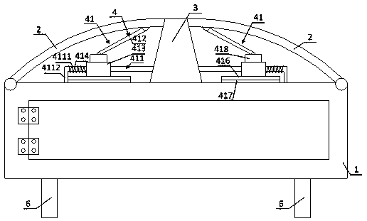
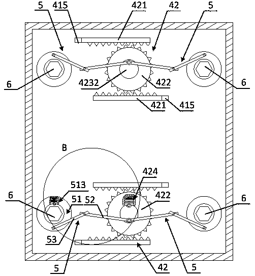
[0023] see Figure 1 to Figure 4 , which shows the preferred structure of the road speed bump provided by the embodiment of the present invention. As shown ...


PUM


Abstract

The invention provides a road deceleration strip. The road deceleration strip comprises a pre-buried box, a supporting block and two deceleration strip bodies. The supporting block is arranged and connected to the upper portion of the pre-buried box. The two deceleration strip bodies are symmetrically arranged ay the two sides of the supporting block, and the two deceleration strip bodies are connected with the pre-buried box through pivots. The two deceleration strip bodies are in transmission connection through a damping buffer mechanism, and the damping buffer mechanism is used for drivingthe other deceleration strip body to rotate when a vehicle passes through one deceleration strip body. Transmission connection between the two deceleration strip bodies is achieved through the dampingbuffer mechanism; the two deceleration strip bodies are arranged on the supporting block, so that when the vehicle passes through one deceleration strip body, the other deceleration strip body is driven to rotate, the two deceleration strip bodies and the supporting block are of an arch structure, the deceleration effect is achieved, damping and buffering are conducted on the vehicle through thedamping and buffering mechanism, the vehicle is protected, and damage to the vehicle is reduced.

Description

technical field [0001] The present invention relates to the technical field of ETC, in particular to a road deceleration belt. Background technique [0002] ETC (Electronic Toll Collection) non-stop toll collection system is an automatic toll collection system for highways or bridges. Through the dedicated short-range communication between the vehicle-mounted electronic tag installed on the vehicle windshield and the microwave antenna on the ETC lane of the toll station, it uses a computer The network technology and the bank carry out background settlement processing, so as to achieve the purpose of paying the expressway or bridge toll without stopping the vehicle through the expressway or bridge toll station. For this reason, a deceleration belt with a certain width and a convex belt is laid on the place where deceleration is required. When the vehicle passes here, it must decelerate properly in order to reduce its peak wave, thereby greatly reducing the possibility of traf...

Claims


Application Information

Patent Timeline
Patent Type & Authority Applications(China)
IPC IPC(8): E01F9/529
CPCE01F9/529
Inventor 于佳意
Owner AEROSPACE INFORMATION
Why Eureka
Try Eureka