Drive unit

A drive unit and component technology, applied in the direction of power devices, electric power devices, jet propulsion devices, etc., can solve the problems of not being able to block the vibration of the motor, and cannot ensure the support strength and rigidity, so as to improve diversity, suppress vibration and vibration sound, the effect of improving ease of use

Pending Publication Date: 2020-05-19
HONDA MOTOR CO LTD
View PDF5 Cites 0 Cited by
  • Summary
  • Abstract
  • Description
  • Claims
  • Application Information

AI Technical Summary

Problems solved by technology

Along with this, the desired support strength and rigidity may not be ensured
In addition, since the connecting mount or the cross member of the torsion bar is supported by the left and right side frames of the connecting mount, there is a possibility that the vibration of the motor cannot be sufficiently blocked from the vehicle body.

Method used


Image

  • Drive unit
  • Drive unit
  • Drive unit

Examples


Embodiment Construction

[0031] Hereinafter, a drive unit according to an embodiment of the present invention will be described with reference to the drawings.

[0032] The drive unit according to the embodiment of the present invention is mounted on, for example, the vehicle 1 . The vehicle 1 is, for example, an electric vehicle such as an electric vehicle, a hybrid vehicle, or a fuel cell vehicle. Electric vehicles are powered by batteries. A hybrid vehicle is driven by a battery and an internal combustion engine as power sources. A fuel cell vehicle is driven by a fuel cell as a driving source.

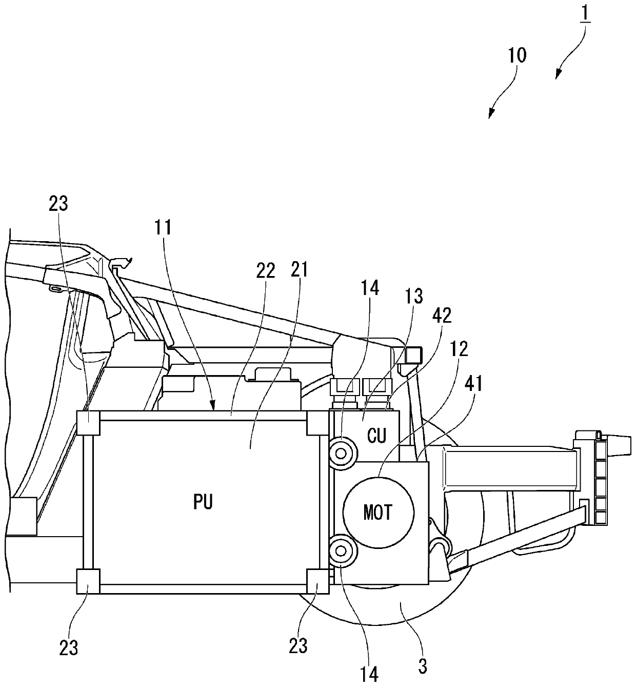
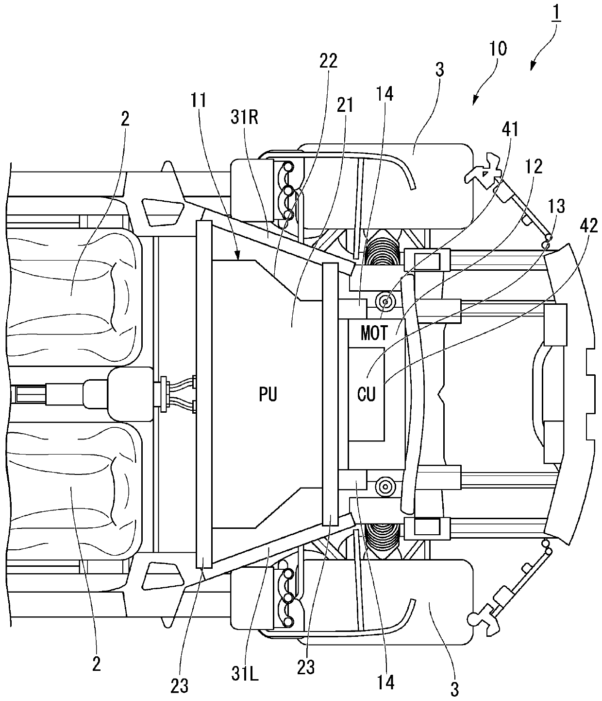
[0033] figure 1 It is a figure which schematically shows the structure of a part of the vehicle 1 equipped with the drive unit 10 which concerns on embodiment of this invention, and is a figure seen from the left side of the left-right direction of a vehicle. figure 2 It is a figure which schematically shows the structure of a part of the vehicle 1 equipped with the drive unit 10 which concerns on emb...


PUM


Abstract

The present invention provides a drive unit capable of suppressing vibration transmitted from a travel drive motor to a vehicle body and capable of appropriately supporting a torque reaction force ofthe motor. A drive unit (10) is provided with a battery (21), a battery exterior member (22), a motor (12), a motor exterior member (41), and at least one connection member (14). The battery exteriormember (22) houses the battery (21). The motor exterior member (41) houses the motor (12). The connection member (14) connects the battery exterior member (22) and the motor exterior member (41).

Description

technical field [0001] The invention relates to drive units. Background technique [0002] Conventionally, there is known a motor fixing seat structure for an electric vehicle comprising: a motor for driving driving having a drive shaft extending in the vehicle width direction; a fixing base; and a torsion bar connecting the outer peripheral portion of the motor to the beam (for example, refer to Japanese Patent Application Laid-Open No. 5-319103). In the structure of the motor fixing seat, the fixing seat blocks the micro-vibration of the motor, and the torsion bar restrains the rotational displacement caused by the driving reaction force of the motor. [0003] According to the motor mount structure according to the conventional art described above, the mount supporting the drive shaft of the motor is formed so as to be vulnerable to positively release the support of the motor when a predetermined or greater impact load acts. Along with this, desired support strength and ...

Claims


Application Information

Patent Timeline
Patent Type & Authority Applications(China)
IPC IPC(8): B60K1/00
CPCB60K1/00B62D25/087B60K1/04B60K2001/0438B60K5/12B62D21/152B60K2001/0416B62D21/09B62D21/02
Inventor 松冈英树蔺牟田幸嗣
Owner HONDA MOTOR CO LTD
Why Eureka
Try Eureka